Lifting-type decelerator

A reducer and lift-type technology, which is used in lifting frames, lifting devices, mechanical equipment, etc., can solve the problems of the collision between the reducer and the fixed seat, the violent vibration of the reducer, and the poor flexibility of use, etc., to achieve strong reliability and reduce vibration. And the effect of noise and stability

Pending Publication Date: 2020-01-31
DONGGUAN TIANYI MOTOR
View PDF0 Cites 1 Cited by
  • Summary
  • Abstract
  • Description
  • Claims
  • Application Information

AI Technical Summary

Problems solved by technology

[0002] Ordinary mechanical transmission, precision instrument precision mechanical transmission, mechanical transmission of mechanical arm, etc. generally use reducers for power transmission and speed adjustment. Traditional reducers include circular gear reducers, worm gear reducers, cycloid reducers, and NGW planetary reducers. Gear reducer, etc. At present, the mounting flange of the reducer is usually directly and rigidly connected to the fixed seat. Under high-speed operation, the reducer will generate severe vibration, which will cause the reducer to collide with the fixed seat, which will easily lead to easy damage inside the reducer or loose parts. , which affects the processing of parts; in addition, the position of the current reducer body cannot be adjusted after installation, and the flexibility of use is poor.

Method used


Image

  • Lifting-type decelerator
  • Lifting-type decelerator
  • Lifting-type decelerator

Examples


Embodiment Construction

[0030] In order to facilitate the understanding of those skilled in the art, the present invention will be further described below in conjunction with the embodiments and accompanying drawings, and the contents mentioned in the embodiments are not intended to limit the present invention. The present invention will be described in detail below in conjunction with the accompanying drawings.

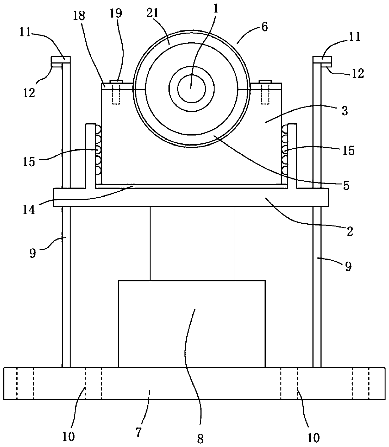
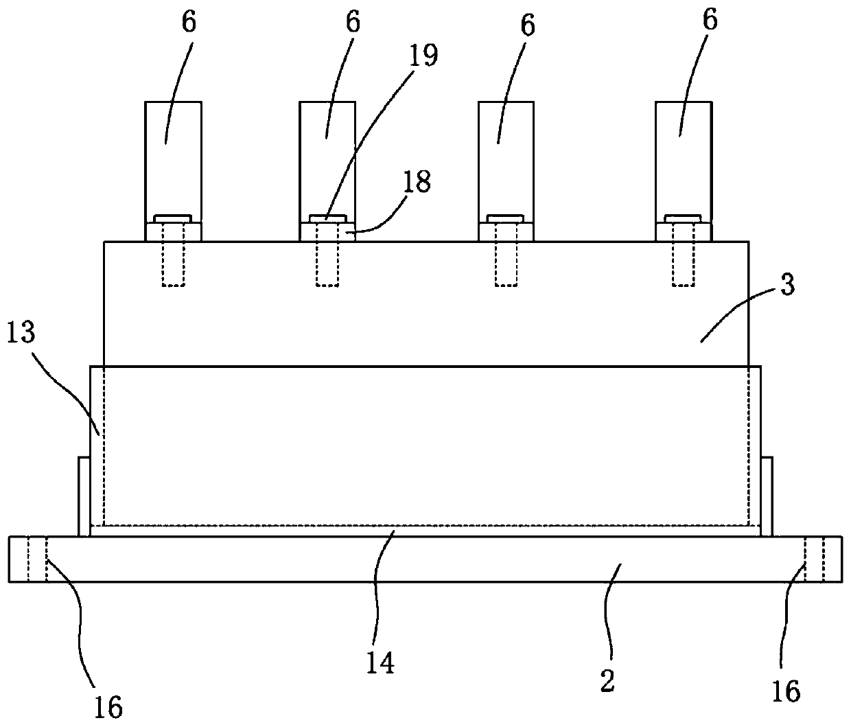
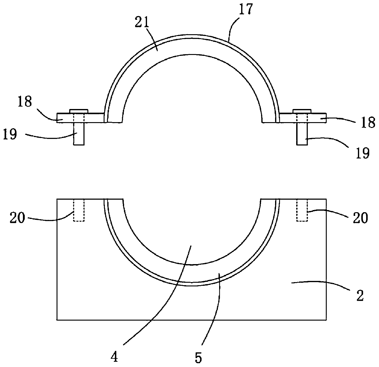
[0031] A lifting reducer, such as Figure 1 to Figure 4 As shown, it includes a reduction body 1, a lifting seat 2, a fixed seat 3 and a lifting assembly, the fixed seat 3 is installed on the lifting seat 2, and the fixed seat 3 is provided with a The fixed groove 4, the inner wall of the fixed groove 4 is provided with the first shock absorber 5, and the fixed base 3 is provided with a plurality of fixed parts 6 for fixing the speed reducer body 1 in a row, and the fixed parts 6 are connected with the fixed parts. The seat 3 is detachably connected; the lifting assembly includes a bottom ...


PUM


Abstract

The invention relates to the technical field of decelerators, in particular to a lifting-type decelerator. The lifting-type decelerator comprises a decelerator body, a lifting seat, a fixing seat anda lifting assembly; the fixing seat is mounted on the lifting seat, and a fixing groove used for mounting the decelerator body is formed in the fixing seat; a first damping body is arranged on the inner wall of the fixing groove, a plurality of fixing pieces used for fixing the decelerator body are arranged on the fixing seat in a row, and the fixing pieces and the fixing seat are detachably connected; the lifting assembly comprises a bottom plate and a lifting driving piece which is used for driving the lifting seat to move up and down; and guiding rods are arranged on the two sides of the bottom plate and movably arranged in the lifting seat in a penetrating mode. The lifting-type decelerator is novel in structure and ingenious in design, the up-down position of the decelerator body is controlled to be adjusted, and using is convenient and reliable; vibration and noise generated during working of the decelerator body are reduced; and the decelerator body is prevented from being loosened, stability is good, and reliability is high.

Description

technical field [0001] The invention relates to the technical field of reducer devices, in particular to an elevating reducer. Background technique [0002] Ordinary mechanical transmission, precision instrument precision mechanical transmission, mechanical transmission of mechanical arm, etc. generally use reducers for power transmission and speed adjustment. Traditional reducers include circular gear reducers, worm gear reducers, cycloid reducers, and NGW planetary reducers. Gear reducer, etc. At present, the mounting flange of the reducer is usually directly and rigidly connected to the fixed seat. Under high-speed operation, the reducer will generate severe vibration, which will cause the reducer to collide with the fixed seat, which will easily lead to easy damage inside the reducer or loose parts. , which affects the processing of parts; in addition, the position of the current reducer body cannot be adjusted after installation, and the flexibility of use is poor. Co...

Claims


Application Information

Patent Timeline
Patent Type & Authority Applications(China)
IPC IPC(8): F16H57/025F16H57/028B66F7/18B66F7/28F16H57/04
CPCB66F7/18B66F7/28F16H57/025F16H57/028F16H57/0412
Inventor 尹东明
Owner DONGGUAN TIANYI MOTOR
Why Eureka
Try Eureka