Multifunctional data converter

A data converter and multi-functional technology, which is applied in the field of data communication, can solve problems such as too long data lines, entanglement, data loss, etc., and achieve the effect of improving stability

Active Publication Date: 2020-01-31
SHANDONG QINCHENG INFORMATION TECH CO LTD
View PDF14 Cites 4 Cited by
  • Summary
  • Abstract
  • Description
  • Claims
  • Application Information

AI Technical Summary

Problems solved by technology

[0003] In the prior art, the notification number is CN1495971A discloses a converter, which has a head that can be connected to an external data bus and one or more connection modules, and the connection modules can be installed in a row and connected to the head in a plug-in manner, wherein , the head has a plug connector with a plug contact connected to the internal data bus; each connection module has a reverse plug connector that matches the plug connector of the head; the reverse plug connector The reverse plug contacts of the connecting module are connected to the circuit connection contacts for connection with the circuit protection with an electronic circuit, and the plug contacts for connecting with the reverse plug contacts of another connection module; each connection module has At least one device connector for connection with the operating mechanism or sensor, communicating with the control device via internal and external buses, although the patented plug connection of the connection modules to each other or between the connection modules and the head and the plug connection of the circuit protection The connection is watertight, but there are still defects. When the data line and the converter are plugged together, it is likely that the data line will be separated from the converter due to some external factors, resulting in data loss.
[0004] When the existing data converter is used, the data cable plug is inserted into the jack of the converter, but because the data cable and the plug are not fixed, sometimes the data cable may be detached from the converter due to some human or external factors. The socket may cause data loss, the stability is not good, and some data lines are too long, which is easy to be entangled and cause inconvenience during use. In order to solve the above problems, we propose a multifunctional data converter

Method used


Image

  • Multifunctional data converter
  • Multifunctional data converter
  • Multifunctional data converter

Examples


Embodiment 1

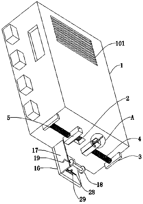
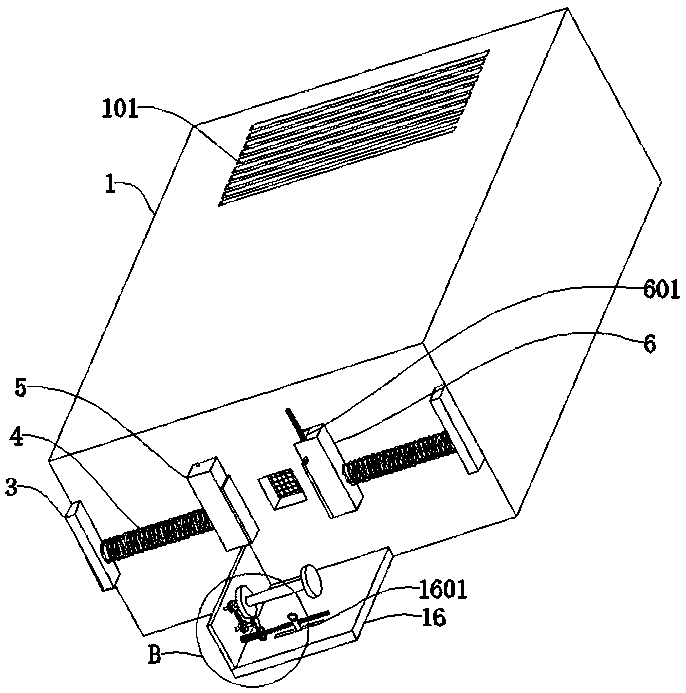
[0033] refer to Figure 1-3, a multifunctional data converter, comprising a converter main body 1, a jack 2 is drilled on the side wall of the converter main body 1, a symmetrically arranged partition 3 is connected to the side wall of the converter main body 1, and a partition 3 is arranged on the side wall of the partition board 3 The first spring 4 is connected, and the ends of the two sets of first springs 4 away from the separator 3 are respectively connected with the first pressing block 5 and the second pressing block 6, and the top of the second pressing block 6 has a rotating groove 601, and the side of the rotating groove 601 The wall is rotatably connected with a rotating shaft 7, the side wall of the rotating shaft 7 is connected with a rack plate 8, the side wall of the second pressing block 6 is connected with a fixed assembly matched with the rotating shaft 7, and a cavity is opened inside the first pressing block 5, The inner wall of the first briquetting block...

Embodiment 2

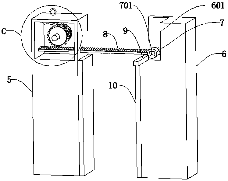
[0037] refer to image 3 , a multifunctional data converter, which is basically the same as Embodiment 1, the difference is that the fixed assembly includes a square post 9, the square post 9 is slidably connected to the side wall of the rotating groove 601, and the side wall of the rotating shaft 7 is dug with a square The square groove 701 matched with the column 9;

[0038] When the rotating shaft 7 is rotated, the square column 9 is pulled out of the square groove 701, and when the rotating shaft 7 drives the rack plate 8 to move to a horizontal position, the square column 9 is inserted into the square groove 701, so that the rotating shaft 7 and the rack Plate 8 is fixed.

Embodiment 3

[0040] refer to Image 6 , a multifunctional data converter, basically the same as Embodiment 2, the difference is that the limit assembly includes a ratchet 13 and a pawl 14, the ratchet 13 is connected to the wall of the rotating rod 11, and the ratchet 14 is rotatably connected to the second On the inner wall of a pressing block 5, the ratchet 13 is engaged with the pawl 14;

[0041] The top of the first briquetting block 5 is connected with a stay cord 15, and the stay cord 15 passes through the top wall of the first briquetting block 5 and is connected to the top of the ratchet 14;

[0042] Since the ratchet 14 will block the ratchet 13 so that the rotating rod 11 and the first gear 12 cannot rotate in the opposite direction, the rack plate 8 cannot move in the opposite direction, so that the first pressing block 5 and the second pressing block 6 can only move toward each other Clamp the plug, but cannot move it in the reverse direction to release the plug. If you need t...


PUM


Abstract

The invention discloses a multifunctional data converter, and belongs to the technical field of data communication. The multifunctional data converter comprises a converter body. One end of two groupsof first springs far away from the partition plate is respectively connected with a first pressing block and a second pressing block. A rack plate is connected on the side wall of a rotating shaft. Alimiting component is connected on the rod wall of the rotating rod. A winding shaft is connected on the one end of a rocking handle near the jack. A screw rod is connected on the one end of a reciprocating mechanism far away from a first cross rod. A threading block is connected on the rod wall of the screw rod in a threaded way. The first springs can drive the first pressing block and the second pressing block to move toward each other to clamp the plug, the limiting component can limit and fix the first pressing block and the second pressing block, the rocking handle is rotated to drive the winding shaft to wind up the data line and the reciprocating mechanism drives the threading block to be unable to move so that the data line is evenly rolled up, and thus the problem that the data line is excessively long and liable to wind together can be solved and the stability of the connection between the data line and the data converter can be improved.

Description

technical field [0001] The invention relates to the technical field of data communication, in particular to a multifunctional data converter. Background technique [0002] With the development of science and technology, the development of the communication industry is particularly rapid, and there are many communication methods. Data conversion is required in the communication process. The external multi-function data line interface converter for communication computers is a kind of calculator accessories, also known as USB. Interface converter, commonly known as computer, is a modern electronic computing machine for high-speed computing. It can perform numerical calculations, logic calculations, and storage and memory functions. It can run according to programs and process massive data automatically and at high speed. Due to the small number of USB interfaces on the computer, a modern intelligent electronic device needs to use a USB interface converter for cooperation. [...

Claims


Application Information

Patent Timeline
Patent Type & Authority Applications(China)
IPC IPC(8): H01R13/639H01R13/72H01R13/633H01R13/502H01R31/06
CPCH01R13/502H01R13/6335H01R13/639H01R13/72H01R31/06H01R2201/06
Inventor 徐海鹏丁英峰唐华
Owner SHANDONG QINCHENG INFORMATION TECH CO LTD
Why Eureka
Try Eureka