Dyed yarn dip dyeing equipment with carding structure and dip dyeing method of dyed yarn dip dyeing equipment
A dyed yarn and equipment technology, applied in dyed yarn dip-dyeing equipment with a carding structure and its dip-dyeing field, can solve the problems of dyed yarn winding, uneven dyeing of dyed yarn, and inability to adjust the distance between multiple yarns, so as to prevent winding Effect
- Summary
- Abstract
- Description
- Claims
- Application Information
AI Technical Summary
Problems solved by technology
Method used
Image
Examples
Embodiment 1
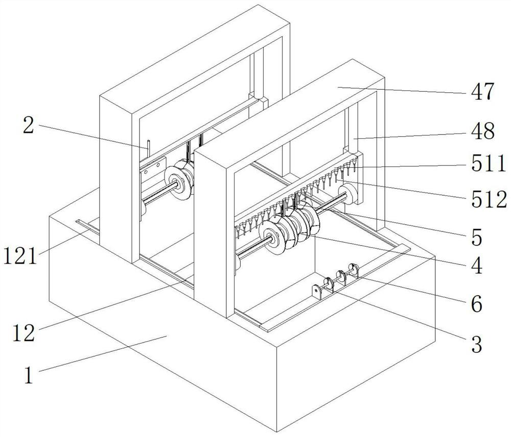
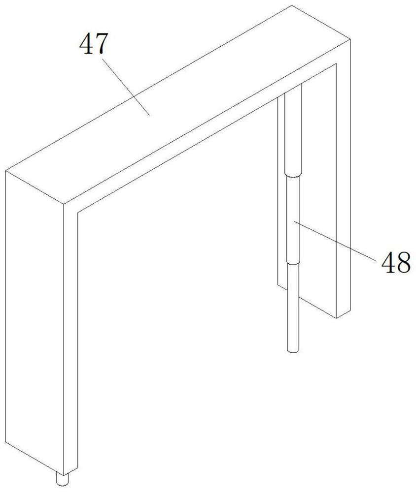
[0038] see Figure 1-5 , Figure 7-9 and Figure 11-14 , This embodiment provides a dyed yarn dyeing equipment with a carding structure and a dyeing method thereof, including a dyeing pool 1 .
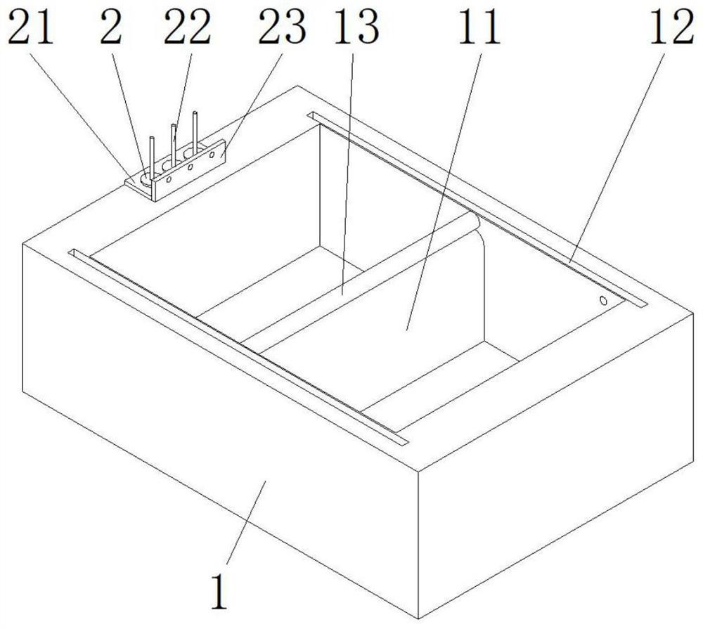
[0039] Wherein, the interior of the dyeing tank 1 is fixedly installed with a partition 11, and the interior of the dyeing tank 1 is divided into two grooves by the partition 11, and the two grooves are respectively used to put dyes and clean water, and the notch of the clean water is opened. There is an opening, the opening is used to connect the hot air blower, and the hot air is blown into the slot.
[0040] In order to facilitate the installation of the yarn, a first installation rod 2 is rotatably installed on the side of the upper end of the dyeing tank 1 close to the dye tank.
[0041] Among them, such as image 3 , Figure 7 As shown, the upper end of the dip-dyeing tank 1 is fixedly connected with a mounting seat 21, the upper end of the mounting seat 21 is rotatably inst...
Embodiment 2
[0076] see Figure 3-6 , made further improvements on the basis of Example 1:
[0077] In order to conveniently adjust the engagement degree of the engagement wheel 41 to the yarn, a sliding threaded sleeve 45 is slidably installed on the outer side wall of the first rotating rod 44 .
[0078] Wherein, the outer side of the first rotating rod 44 is provided with a protruding strip to prevent the sliding threaded sleeve 45 from rotating, and the hole of the sliding threaded sleeve 45 is provided with a chute matching the protruding strip.
[0079] The outer side wall of the sliding threaded sleeve 45 is provided with two sets of threads, and the rotation directions of the two sets of threads are opposite. The clamping wheel 41 includes two first sliding discs 411 and elastic strips 412. At the edge of one side of the first sliding plate 411 , there are a plurality of elastic strips 412 , which are evenly arranged in a circular array at the center of the first sliding plate 411 ....
Embodiment 3
[0084] see figure 1 , Figure 15 , made further improvements on the basis of Example 1:
[0085] In order to prevent the water in the groove from being dyed by the dye on the yarn for a long time, the rinsing effect is reduced, a pipe 511 is fixedly connected to one side of the cross bar 51 located on the groove of the clean water.
[0086] Among them, the pipe 511 is used to connect the water pipe, the lower end of the pipe 511 is fixedly connected with a plurality of nozzles 512, the nozzles 512 are vertically downward, no fresh water will be put into the original groove with clean water, and there is a drainage outlet at the bottom of the groove, through the nozzles 512 When spraying the yarn coming out of the dye, since the spray head 512 is vertically downward, the water flow provides a downward force to the yarn when it contacts the yarn, so that the yarns will not approach each other. At the same time, the yarn is combed.
PUM
 Abstract
Description
Claims
Application Information
 - R&D
- Intellectual Property
- Life Sciences
- Materials
- Tech Scout
- Unparalleled Data Quality
- Higher Quality Content
- 60% Fewer Hallucinations
Browse by: Latest US Patents, China's latest patents, Technical Efficacy Thesaurus, Application Domain, Technology Topic, Popular Technical Reports.
© 2025 PatSnap. All rights reserved.Legal|Privacy policy|Modern Slavery Act Transparency Statement|Sitemap|About US| Contact US: help@patsnap.com


