Energy-saving pest elimination equipment with cleaning function

An energy-saving and insect-killing technology, which is applied in the direction of cleaning methods using tools, cleaning methods and appliances, and support structures for photovoltaic modules, can solve the problem of reducing the energy-saving and environmental protection of insect-killing equipment, reducing the convenience of insect-killing equipment, and reducing the number of users. Increase the workload and other issues, to achieve the effect of improving convenience, improving practicality, improving energy saving and environmental protection

Inactive Publication Date: 2020-02-04
刘彦杰
View PDF8 Cites 1 Cited by
  • Summary
  • Abstract
  • Description
  • Claims
  • Application Information

AI Technical Summary

Problems solved by technology

[0003] Most of the existing pest control equipment relies on the power supply of the urban power grid, which consumes a large amount of electric energy, which reduces the energy saving and environmental protection of the existing pest control equipment. Not only that, but the existing pest control equipment usually uses the power grid to kill the insects, resulting in insects The corpses of dead insects adhere to the power grid and need to be cleaned manually, which increases the work burden for users and reduces the convenience of existing pest control equipment.

Method used


Image

  • Energy-saving pest elimination equipment with cleaning function
  • Energy-saving pest elimination equipment with cleaning function
  • Energy-saving pest elimination equipment with cleaning function

Examples


Embodiment Construction

[0025] The present invention is described in further detail now in conjunction with accompanying drawing. These drawings are all simplified schematic diagrams, which only illustrate the basic structure of the present invention in a schematic manner, so they only show the configurations related to the present invention.

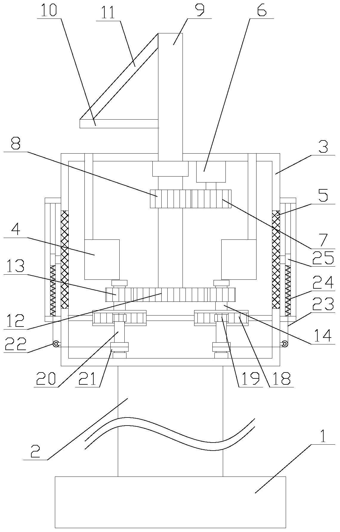
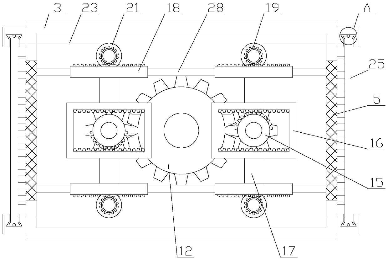
[0026] Such as figure 1 As shown, an energy-saving pest control device with a cleaning function includes a main body 3, a support column 2, a chassis 1, two fixed boxes 4 and two power grids 5, and the support column 2 is vertically fixed above the chassis 1 , the main body 3 is fixed on the top of the support column 2, openings are provided on both sides of the main body 3, the openings correspond to the grid 5 one by one, the grid 5 is fixedly connected to the inner wall of the opening, and the fixed box 4 is fixed inside the main body 3, and the top of the fixed box 4 is provided with a feeding port, and the fixed box 4 is provided with some air holes, and...


PUM


Abstract

The invention relates to energy-saving pest elimination equipment with a cleaning function. The equipment comprises a body, a supporting column, a base plate, two fixing boxes, two electrified wire nets, a cleaning mechanism and an energy-saving mechanism. The energy-saving mechanism comprises a solar panel, a driving gear, a strut, a supporting rod, a first bearing and a driving component. The cleaning mechanism comprises two moving components and two transmission components. Each moving component comprises a scraper, two springs, two limiting units and two moving units. The energy-saving pest elimination equipment with the cleaning function has advantages that by the cleaning mechanism, a function of cleaning the electrified wire nets is realized, influences on normal operation of the electrified wire nets due to adhesion of mosquito bodies on the electrified wire nets are avoided while manual cleaning is avoided, and accordingly convenience in cleaning is achieved; by the energy-saving mechanism, a function of solar power generation is realized, and electric energy can be supplied to the equipment, so that energy saving is realized, energy efficiency and environmental friendliness are improved, failure in normal operation of the equipment due to urban power failure can be avoided, and practicality of the equipment is improved.

Description

technical field [0001] The invention relates to the field of new energy equipment, in particular to an energy-saving pest control equipment with a cleaning function. Background technique [0002] New energy (NE): also known as unconventional energy. Refers to various forms of energy other than traditional energy. Refers to energy sources that have just begun to be developed and utilized or are being actively researched and yet to be promoted, such as solar energy, geothermal energy, wind energy, ocean energy, biomass energy, and nuclear fusion energy. [0003] Most of the existing pest control equipment relies on the power supply of the urban power grid, which consumes a large amount of electric energy, which reduces the energy saving and environmental protection of the existing pest control equipment. Not only that, but the existing pest control equipment usually uses the power grid to kill the insects, resulting in insects The corpses of the dead insects adhere to the po...

Claims


Application Information

Patent Timeline
Patent Type & Authority Applications(China)
IPC IPC(8): A01M1/02A01M1/22B08B1/00H02S20/30
CPCA01M1/02A01M1/223B08B1/002H02S20/30Y02E10/50
Inventor 刘彦杰
Owner 刘彦杰
Why Eureka
Try Eureka