Quick-connection structure

A connection structure and clamping groove technology, applied in the field of quick-connect structure and power device quick-connect structure, can solve the problem that electrical appliances or machinery cannot share the same power device, reduce the trouble of removing fasteners such as bolts, and improve the Efficiency, cost reduction effect

Pending Publication Date: 2020-02-04
YONGKANG GUANGYI TECH CO LTD
View PDF0 Cites 2 Cited by
  • Summary
  • Abstract
  • Description
  • Claims
  • Application Information

AI Technical Summary

Problems solved by technology

[0003] For this reason, the embodiment of the present invention provides a quick connection structure to solve the problem in the prior art that many different electrical appliances or machines cannot share the same power device

Method used


Image

  • Quick-connection structure
  • Quick-connection structure
  • Quick-connection structure

Examples


Embodiment 1

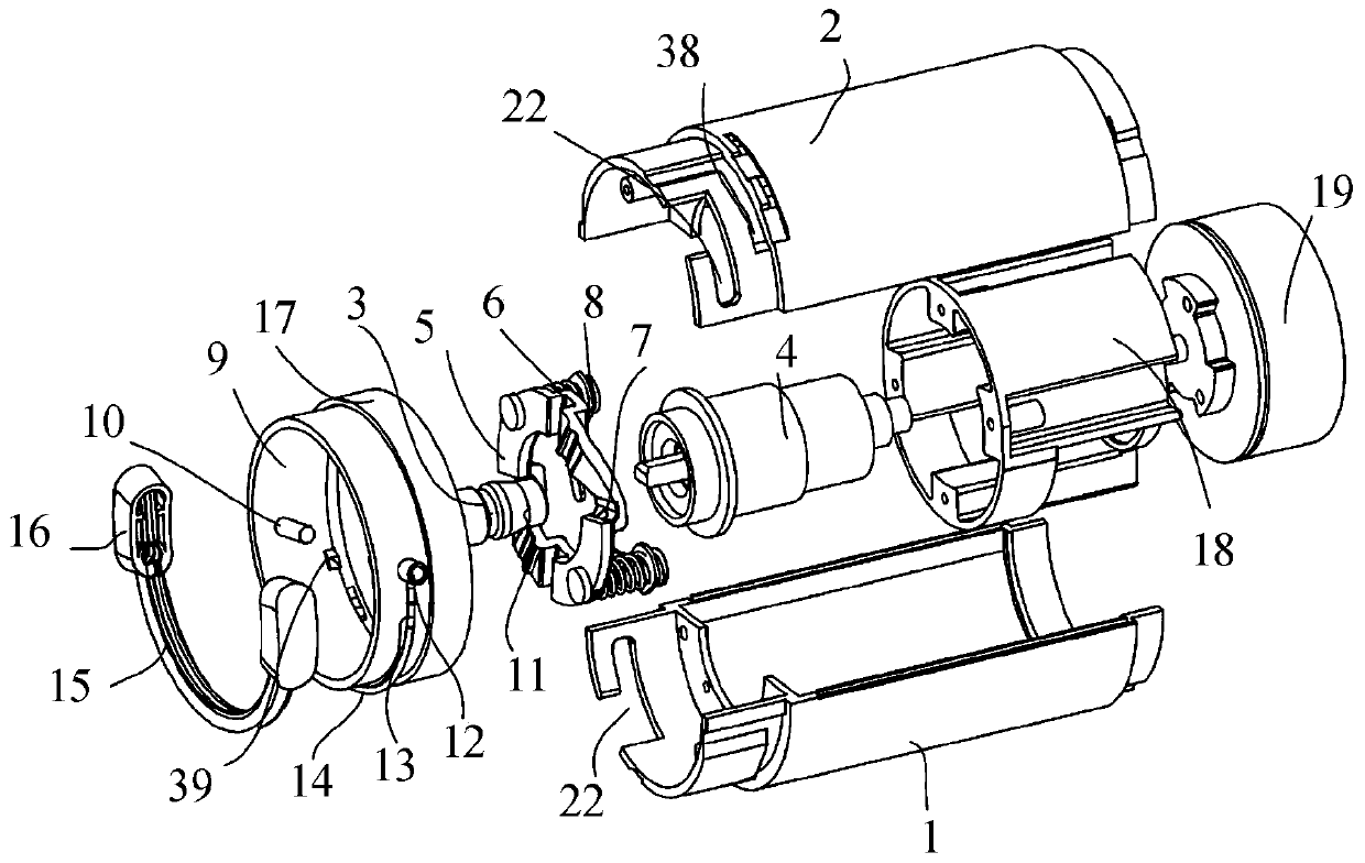
[0032] Such as Figure 1 to Figure 7 As shown, a quick-connect structure in this embodiment includes an upper housing 2, a lower housing 1, a power unit 19, an inner quick-connect assembly 4, a rotary stopper 5, two first springs 6, and a functional housing 9 and functional shaft sleeve 11; the upper casing 2 and the lower casing 1 are fastened and connected to form a casing part, and a first accommodation chamber is arranged in the casing part, and the power unit 19 is arranged in the first accommodation chamber, and the output shaft of the power unit 19 Insert one end of the inner quick-connect assembly 4, and the other end of the inner quick-connect assembly 4 is inserted into the functional bushing 11; the rotary stopper 5 is elastically connected to one end of the housing part through two first springs 6, and the housing The side wall located on the outside of the rotary baffle 5 is provided with two engagement grooves 22, and two engagement pins 10 are fixed on the inner...

Embodiment 2

[0036] Such as Figure 1 to Figure 7 As shown, a quick connection structure in this embodiment includes all the technical features in Embodiment 1. In addition, a plurality of barbs are also provided on the outer wall of the end of the shell part provided with the locking groove 22. Slot 38, a plurality of barb grooves 38 are located on the rear side of the engaging groove 22, a plurality of engaging protrusions 39 are arranged on the inner wall of the functional housing 9, and the number of the barb grooves 38 is the same as that of the engaging protrusions 39 ; when the locking pin 10 on the functional shell 9 is rotated and locked in the locking groove 22, the locking protrusion 39 on the functional shell 9 is correspondingly locked in the barb groove 38 to realize the connection between the functional shell 9 and the housing part. When the functional housing 9 is disassembled, the functional housing 9 is pushed towards the direction of the power unit 19, the functional bus...

Embodiment 3

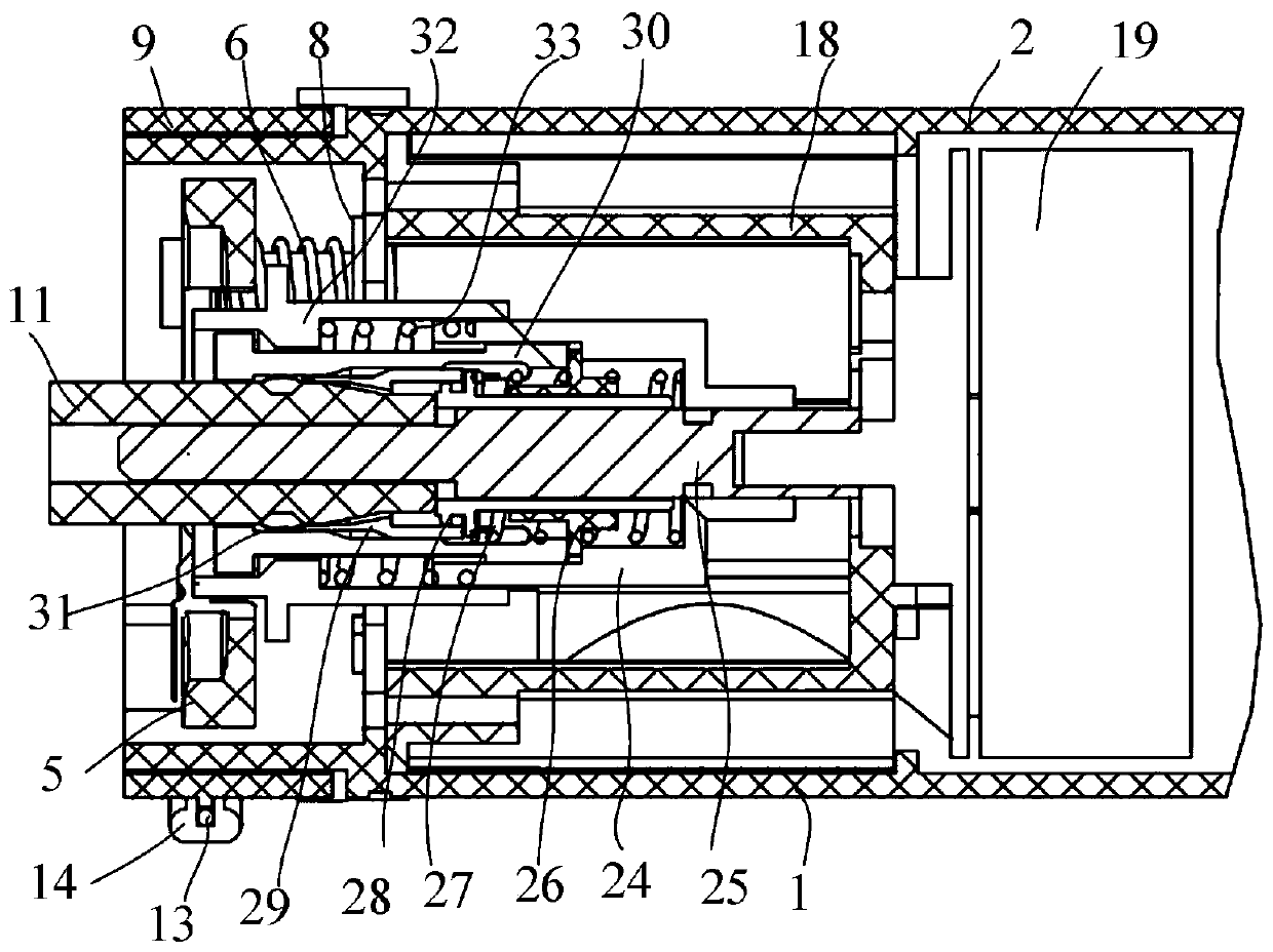
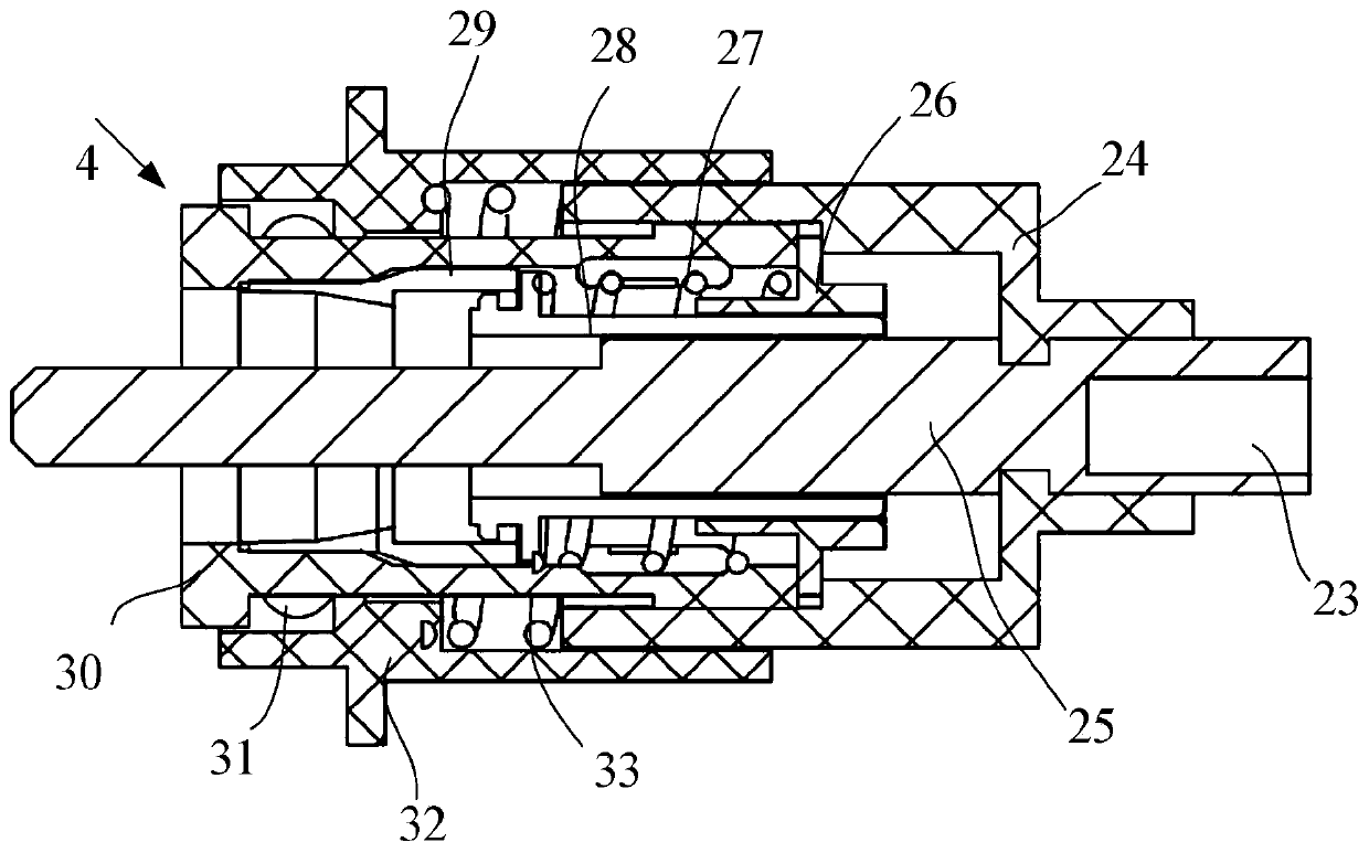
[0040] Such as Figure 1 to Figure 7 As shown, a quick-connect structure in this embodiment includes all the technical features in Embodiment 2. In addition, the inner quick-connect assembly 4 includes an inner quick-connect sleeve 24, an inner quick-connect shaft 25, an inner quick-connect Base 26, second spring 27, inner quick-connect spring post 28, inner quick-connect washer 29, inner quick-connect lower cover 30, multiple steel balls 31, inner quick-connect upper cover 32 and third spring 33; inner quick-connect sleeve 24 Fixed on the outer peripheral side of the inner quick-connect shaft 25, one end of the inner quick-connect shaft 25 is provided with a motor shaft hole 23, the output shaft of the power unit 19 is plugged in the motor shaft hole 23, and the other end outer wall of the inner quick-connect shaft 25 An annular accommodation cavity is formed between the inner quick-connect sleeve 24 , the inner quick-connect base 26 is sleeved on the outer peripheral side of...


PUM


Abstract

The invention discloses a quick-connection structure. An upper shell and a lower shell are buckled to form a shell part, a first containing cavity is formed in the shell part, a power device is arranged in the first containing cavity, an output shaft of the power device is inserted in one end of an inner quick-connection assembly, and the other end of the inner quick-connection assembly is inserted in a function shaft sleeve; a rotation block disc is elastically connected to one end of the shell part through two first springs, two clamping grooves are formed in the side wall, on the outer sideof the rotation block disc, of the shell part, and two clamping pins are fixed to the inner side wall of a function shell and correspond to the clamping grooves; and when the clamping pins are clamped into the clamping grooves, the clamping pins abut against the rotation block disc. The aim is to solve the problem that in the prior art, multiple different electric appliances or machines cannot share the same power device. The quick-connection structure has the advantages that one machine achieves a multi-purpose function, the energy is saved, the emission is reduced, resource waste is reduced, function heads are automatically identified, power required by different function heads is provided, and the quick-connection structure is suitable for various household appliances, electric tools and large-scale function machines.

Description

technical field [0001] Embodiments of the present invention relate to the technical field of quick connection structures for power devices, and in particular to a quick connection structure. Background technique [0002] At present, there are many kinds of household appliances, electric tools and large-scale power machinery. Different household appliances, electric tools and large-scale power machinery need to be equipped with separate power devices; among them, household appliances such as fascia guns, hedge trimmers, dual vibration massagers, Rotary scrubbers, light mixers, heavy mixers, electric fans, noodle makers, etc.; the above-mentioned household appliances are used alone, and can only be used for a certain function, and cannot be converted to other tools or appliances; electric tools such as electric drills , screwdriver, electric wrench, electric grinder, electric hammer, electric pick, electric planer, electric saw, electric scissors, electric wood milling, mixer,...

Claims


Application Information

Patent Timeline
Patent Type & Authority Applications(China)
IPC IPC(8): B25F3/00
CPCB25F3/00
Inventor 傅珂珂李进
Owner YONGKANG GUANGYI TECH CO LTD
Why Eureka
Try Eureka