Vibration anti-blocking device and method for pneumatic conveying of concrete mortar
A technology of concrete mortar and pneumatic conveying, which is applied in the direction of conveying bulk materials, conveyors, transportation and packaging, etc., can solve the problems of difficult to completely clean up the cement slurry, the reduction of vibration frequency and amplitude, and unfavorable vibration transmission, so as to cover the vibration range. Wide and smooth output, the effect of improving the vibration transmission distance
- Summary
- Abstract
- Description
- Claims
- Application Information
AI Technical Summary
Problems solved by technology
Method used
Image

Examples
Embodiment Construction
[0020] The present invention will be further described below in conjunction with the embodiment in the accompanying drawings:
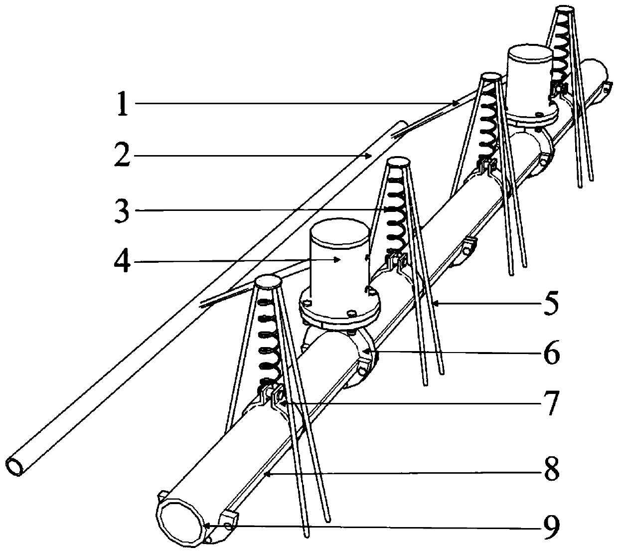
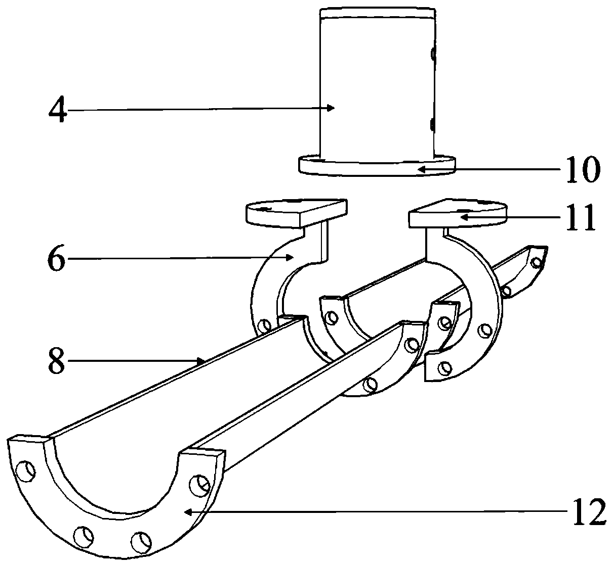
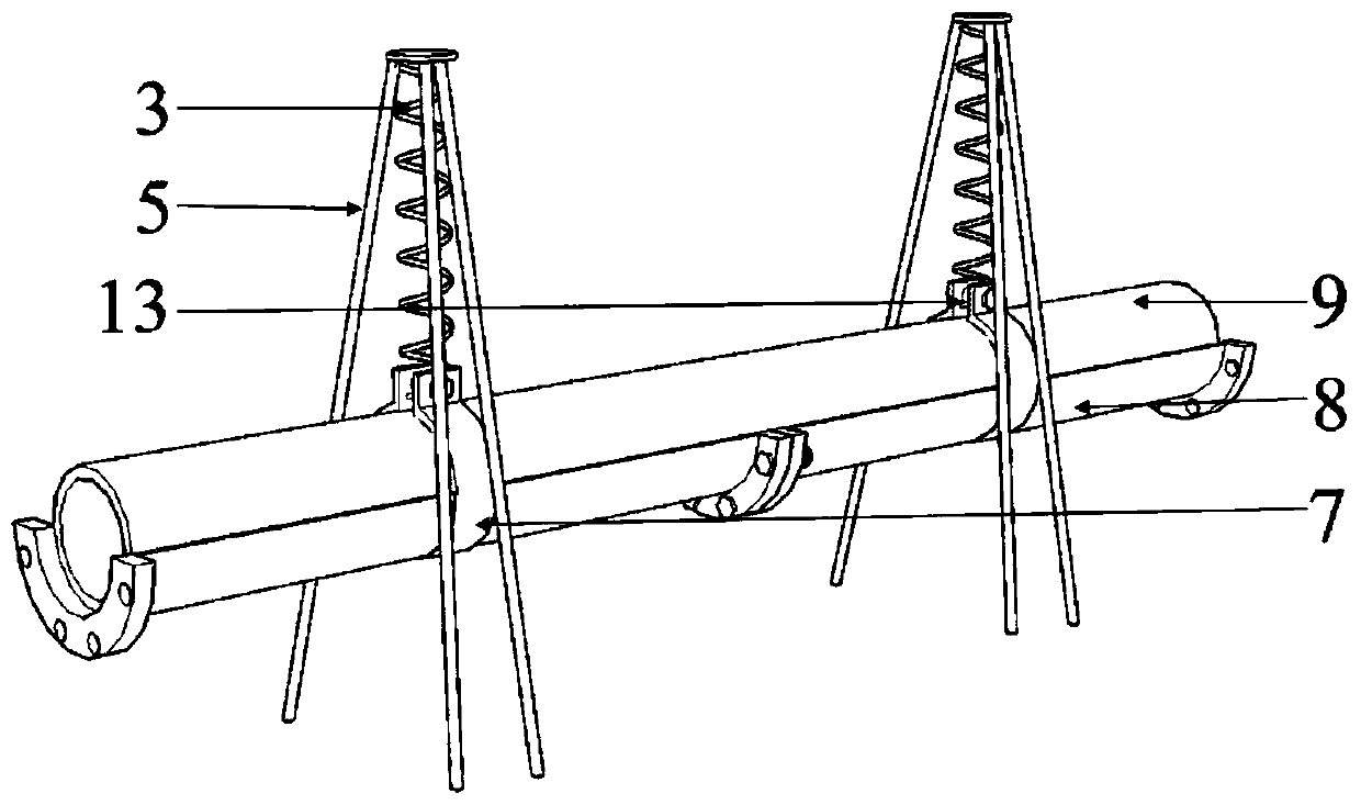
[0021] like figure 1 , 2 Shown in and 3, the anti-blocking device for pneumatically transporting concrete mortar of the present invention mainly consists of a bronchus 1, a main air pipe 2, a pneumatic vibrating device, a tripod elastic vibrating device, a semicircular groove hosting 8, a feeding hose 9 and a vibrator The base 10 is formed; the bottom of the conveying hose 9 is provided with a multi-section semicircular groove trusteeship 8 fixedly connected by a welding flange 12, and the middle part of the multi-section semicircular groove trusteeship 8 is provided with a fixed semicircular groove trusteeship and a material conveyance hose The elastic vibration device of the tripod on the upper part, a plurality of pneumatic vibration devices fixed at the position of the welding flange 12 are inserted between the elastic vibration devices of the tr...
PUM
 Abstract
Description
Claims
Application Information
 - R&D
- Intellectual Property
- Life Sciences
- Materials
- Tech Scout
- Unparalleled Data Quality
- Higher Quality Content
- 60% Fewer Hallucinations
Browse by: Latest US Patents, China's latest patents, Technical Efficacy Thesaurus, Application Domain, Technology Topic, Popular Technical Reports.
© 2025 PatSnap. All rights reserved.Legal|Privacy policy|Modern Slavery Act Transparency Statement|Sitemap|About US| Contact US: help@patsnap.com