Anti-rollover locking metal support

An anti-rollover and locking technology, applied in the direction of bridge parts, bridges, buildings, etc., can solve the problem of inability to adapt to the elongation and contraction of the beam body, the support cannot be practically used in the viaduct, and the beam body of the viaduct cannot be prevented from rolling over, etc. question

Pending Publication Date: 2020-02-04
陈洋哲
View PDF0 Cites 1 Cited by
  • Summary
  • Abstract
  • Description
  • Claims
  • Application Information

AI Technical Summary

Problems solved by technology

[0015] In the current prior art, there is also a bridge anti-overturning support and its construction method with the patent No. CN2015105183408, but it is to fix the whole support with the beam body and the cover beam through screws, although it can prevent the beam of the viaduct The body rolls over, but the beam body cannot slide back and forth on the support and cannot adapt to the elongation and contraction caused by the thermal expansion and contraction of the beam body, so that the beam body is easy to pull or push the pier, and then the support Can not be practically applied to the construction of viaducts
There is also a bridge anti-overturning support with the patent number CN2016104866163, but it prevents the overturning of the beam body during an earthquake, and contacts and cooperates through the plug-in boards intersecting each other between the three boards. Cylindrical rollers are used to cooperate with each other to improve the sensitivity of the anti-seismic performance; the brake pads arranged at intervals are used to cooperate between two adjacent plug-in plates, and when an earthquake occurs, the amplitude of the horizontal force of the earthquake is decomposed into high-frequency The low-amplitude vibration improves the anti-seismic performance; but it does not restrict the up and down movement between the three plates and the lateral movement of the beam body, and does not have the function of preventing the beam body of the viaduct from turning over
There is also a curved girder bridge anti-overturning support with the patent number CN2017102968862, but it is hinged and fixed with a connecting rod in the middle of one side of the upper end surface of the rotating sleeve, and two connecting rods 8 are hinged at the middle position of the main bodies of the two supports. The connecting rods 8 hinged and fixed on the rotating sleeves of the two sets of support bodies are respectively in front and behind of the two sets of rotating sleeves; the main body of the support bears the downward pressure of the beam body under the action of partial load, so that the rotating bearing on this side The downward displacement occurs together with the rotating sleeve, and the depressed rotating sleeve makes the canal move upward in the sliding track on the inner wall of the sleeve. The side rotating sleeve 3 is under the reaction force of the canal 5 acting on the sliding track 9 It rotates around the rotating bearing, and then drives the connecting rod 8 on the rotating sleeve 3 to rotate, and then transmits the force to the rotating sleeve on the other side of the support through the hinged two connecting rods, so that the rotating sleeve on the other side rotates around the side The rotating bearing 4 rotates upwards in a spiral, and the rotating force makes the rotation pull down the side beam body to resist the torque generated by the eccentric load; and there is no limit to itself and the fixed support cannot move up and down, there is no The function of preventing the girder body of the viaduct from overturning
There is also a patent No. CN2017202109525 based on a structural self-balancing anti-overturning device for single-column pier bridges. The eccentric load force on one side is transmitted to the other side, so that the force on both sides of the bridge is balanced; it cannot lock the girder body from moving laterally and up and down, and has no function of preventing the girder body of the viaduct from turning over

Method used


Image

  • Anti-rollover locking metal support
  • Anti-rollover locking metal support
  • Anti-rollover locking metal support

Examples


Embodiment Construction

[0080] There are two technical solutions for the anti-rollover locking metal support:

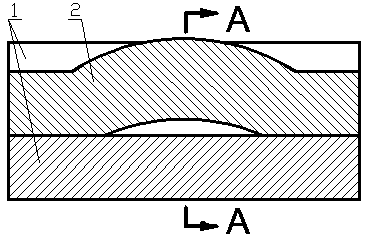
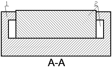
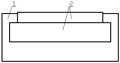
[0081] 1. The anti-rollover locking metal support includes an elastic slide plate 2 composed of a curved plate 7 and a straight plate 8 or a curved plate, a sliding guide part on the elastic slide plate 2, a lateral limit part, a locking limit part 5, and a bearing part The formed guide slide body 1, the guide slide groove 6 on the guide slide base body 1;

[0082] There is a long opening on the long side so that the cross section of the rectangular tubular guide slide body 1 is a convex guide slide groove 6, and an elastic slide plate 2 and an arc-shaped plate 7 of the elastic slide plate 2 are installed in the guide slide groove 6 The top of the top is higher than the upper end of the guide slide seat body 1, the guide slide part of the elastic slide plate 2 is wider than the arc plate 7, and the guide slide part is between the locking limit part 5 of the guide slide groove 6 and the bear...


PUM


Abstract

The invention relates to an anti-rollover locking metal support, and belongs to the technical field of overpasses. An elastic sliding plate or a longitudinal guide sliding block and a wave-like curvedelastic plate are arranged in a guide sliding groove of a guide sliding seat body, and the top of an arc-shaped plate of the elastic sliding plate or the upper end of the longitudinal guide sliding block is higher than the upper end of the guide sliding seat body. The guide sliding parts of the elastic sliding plate or a sliding guide block of the longitudinal guide sliding block are positioned between the lower surface of the locking limiting part of the guide sliding groove and the bearing part of the guide sliding groove and between two transverse limiting parts of the guide sliding groove. The guide sliding parts on the two sides of the elastic sliding plate or the two sides of the longitudinal guide sliding block are locked and limited not to move up and down through the locking limiting part in the guide sliding seat body, then the elastic sliding plate or the longitudinal guide sliding block is limited not to slide to two sides through the transverse limiting parts in the guidesliding seat body, therefore the two sides of a beam body of the overpass with a single pier and a single support supporting the beam body can be locked without swinging up and down, and further thebeam body of the overpass with the single pier and the single support supporting the beam body is locked not to roll over to any side.

Description

technical field [0001] The invention relates to an anti-rollover locking metal support in the technical field of viaducts for railways and highways. Background technique [0002] The construction of expressways and urban interchanges costs a lot, especially the construction cost of the piers of viaducts is high. In order to save construction costs under the condition of limited construction location and saving land use, according to the requirements of construction units, many design units design many piers as single-pier and single-support support types; The overall load exceeds the design load too much, which is often the main reason for the torsional overturning of the viaduct, and the torsional overturning has caused many viaduct rollover accidents. [0003] Between the piers supported by single piers, a combination of fixed supports on one pier and fully floating movable supports on multiple piers is used to make the cover girder (horizontal girder of the lateral suppo...

Claims


Application Information

Patent Timeline
Patent Type & Authority Applications(China)
IPC IPC(8): E01D19/04
CPCE01D19/04
Inventor 陈山冰唐缝梁陈洋哲
Owner 陈洋哲
Why Eureka
Try Eureka