Crushing device of top coal caving hydraulic support

A technology of hydraulic support and crushing device, which is applied in pillars/supports, mining equipment, earthwork drilling and mining, etc. It can solve the problems of small investment in equipment, easy crushing of the roof beam, and low pressure, so as to achieve convenient crushing and prevent damage to the roof beam effect

Active Publication Date: 2020-02-04
HENAN POLYTECHNIC UNIV
View PDF5 Cites 3 Cited by
  • Summary
  • Abstract
  • Description
  • Claims
  • Application Information

AI Technical Summary

Problems solved by technology

[0002] In coal mine machinery and equipment, the top coal caving hydraulic support is stable, the coal opening is continuous, the back loss is small, and the coal caving effect is good. For thick coal seam mining, the equipment investment is small and the cost performance is high. It is suitable for coal seams below medium hardness, joints, cracks There are obviously or well-developed thick coal seams, but in the process of coal mining, it is inevitable to encounter coal seams with high hardness. For coal seams with high hardness, the traditional top-coal caving hydraulic support crushing device exerts less pressure, which cannot actively and effectively break the top-coal and increase the discharge rate of the top-coal. Hard coal blocks are easy to crush the top beam and affect coal mining efficiency

Method used


Image

  • Crushing device of top coal caving hydraulic support
  • Crushing device of top coal caving hydraulic support
  • Crushing device of top coal caving hydraulic support

Examples


Embodiment Construction

[0015] In order to understand the above-mentioned purpose, features and advantages of the present invention more clearly, the present invention will be further described in detail below in conjunction with the accompanying drawings and specific embodiments. It should be noted that, in the case of no conflict, the embodiments of the present application and the features in the embodiments can be combined with each other.

[0016] In the following description, many specific details are set forth in order to fully understand the present invention. However, the present invention can also be implemented in other ways different from those described here. Therefore, the protection scope of the present invention is not limited by the specific details disclosed below. EXAMPLE LIMITATIONS.

[0017] The following combination Figure 1 to Figure 4 The technical solution of the present invention is further described.

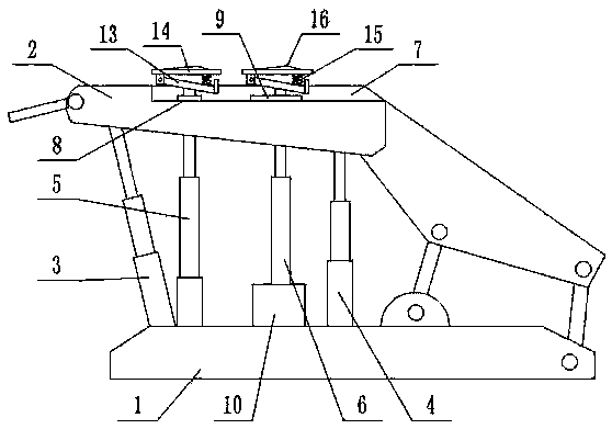
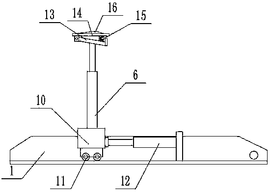
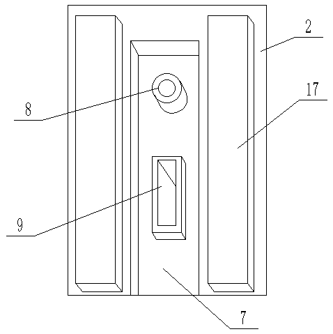
[0018] As shown in the figure, the present invention proposes a crushi...


PUM


Abstract

The invention provides a crushing device of a top coal caving hydraulic support. The crushing device of the top coal caving hydraulic support comprises a base, an ejecting beam, a front telescopic stand column and a rear telescopic stand column, and further comprises an ejecting block device; the ejecting block device comprises a front telescoping ejecting column, a rear telescopic ejecting column, crushing plates at the upper end of the front telescopic ejecting column and the upper end of the rear telescopic ejecting column, wherein a crushing groove located in the middle is arranged at theupper end of the ejecting beam, a front ejecting column sleeve ring and a rear ejecting column moving groove are arranged in the crushing groove, the bottom end of the front telescoping ejecting column is fixed on the base, the telescoping end of the upper end of the front telescoping ejecting column is installed at the front ejecting column sleeve ring, the bottom end of the rear telescopic ejecting column is fixed on a sliding frame, the telescopic end of the upper end of the rear telescopic ejecting column is installed at the rear ejecting column moving groove, the lower end of the slidingframe is provided with sliding wheels, and the right end of the sliding frame is connected with a telescopic end of a movable hydraulic rod fixed on the base. According to the crushing device, a hardcoal seam is conveniently crushed, the crushing device of the top coal caving hydraulic support tightly presses against the coal seam in the moving process of the crushing device of the top coal caving hydraulic support, and the large hard coal briquette is prevented from smashing the ejecting beam.

Description

technical field [0001] The invention relates to the technical field of coal mine machinery and equipment, in particular to a crushing device for hydraulic supports of caving coal. Background technique [0002] In coal mine machinery and equipment, the top coal caving hydraulic support is stable, the coal opening is continuous, the back loss is small, and the coal caving effect is good. For thick coal seam mining, the equipment investment is small and the cost performance is high. It is suitable for coal seams below medium hardness, joints, cracks There are obviously or well-developed thick coal seams, but in the process of coal mining, it is inevitable to encounter coal seams with high hardness. For coal seams with high hardness, the traditional top-coal caving hydraulic support crushing device exerts less pressure, which cannot actively and effectively break the top-coal and increase the discharge rate of the top-coal. Hard coal blocks are easy to crush the top beam and af...

Claims


Application Information

Patent Timeline
Patent Type & Authority Applications(China)
IPC IPC(8): E21D15/44E21C27/20E21D15/55E21D15/50
CPCE21C27/20E21D15/44E21D15/50E21D15/55
Inventor 王蔚张法政范金鹏王岳栩段向永
Owner HENAN POLYTECHNIC UNIV
Why Eureka
Try Eureka