

Air flow adjusting device and air conditioner
A technology for airflow adjustment and air conditioners, which is applied in air conditioning systems, airflow control components, lighting and heating equipment, etc. It can solve the problems of difficult processing of orifice structure or slit structure, large wind resistance, and impact, so as to reduce condensation Phenomenon, strong diffusion ability, effect of improving comfort
- Summary
- Abstract
- Description
- Claims
- Application Information
AI Technical Summary
Problems solved by technology
Method used
Image

Examples
Embodiment 1
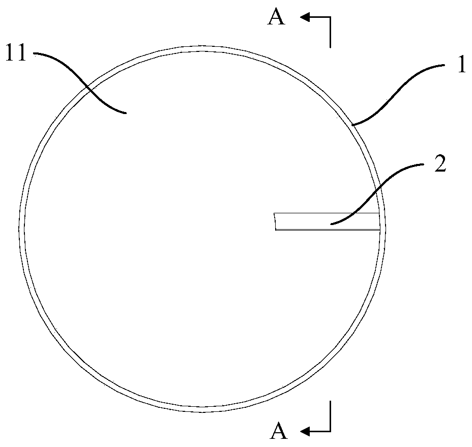
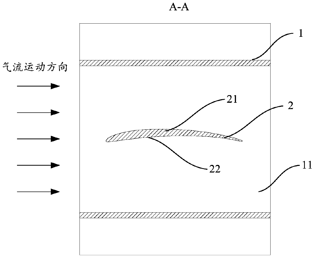
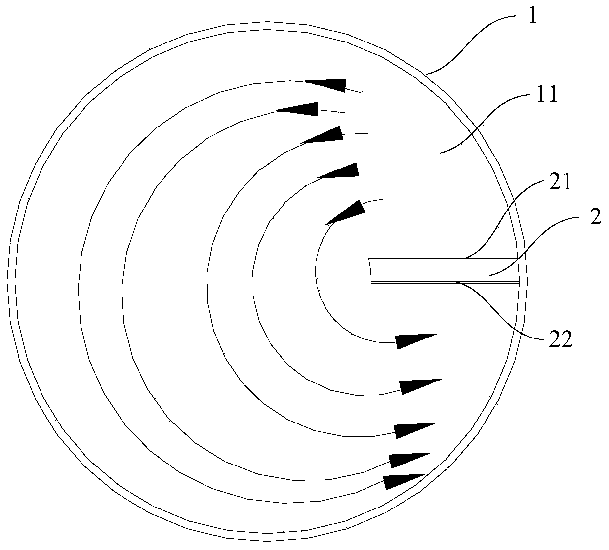
[0057] Provided in this embodiment is an airflow regulating device, such as figure 1 and figure 2 As shown, a housing 1 and a guide structure 2 are included. The casing 1 is provided with an airflow passage 11 , the airflow passage 11 runs through the casing 1 , and the airflow passage 11 has openings at both ends of the casing 1 to communicate with the outside. The inner wall of the housing 1 is provided with a guide structure 2, which protrudes from the inner wall of the housing 1 and extends along the inner wall of the housing 1; the sides of the guide structure 2 located on both sides of its own extension direction face the same The sides are arched so that the side structures on both sides are different. When the airflow regulating device is applied to an air conditioner, the outlet airflow of the air conditioner flows in from one end of the airflow channel 11 and flows out from the other end of the airflow channel 11 . Such as image 3 As shown, the two sides of the...
Embodiment 2
[0059] Provided in this embodiment is an airflow regulating device, such as figure 1 As shown, a housing 1 and a guide structure 2 are included. The casing 1 is provided with an airflow passage 11 , the airflow passage 11 runs through the casing 1 , and the airflow passage 11 has openings at both ends of the casing 1 to communicate with the outside. The cross-section of the airflow passage 11 is circular, and the airflow passage 11 has a cylindrical structure as a whole. The inner wall of the housing 1 is provided with a guide structure 2, and the guide structure 2 protrudes from the inner wall of the housing 1 in a radial direction, and The size of the guide structure 2 in the radial direction is smaller than the radius of the cross-sectional circle of the airflow channel 11 . Such as figure 2 As shown, the guide structure 2 extends along the inner wall surface of the housing 1, and the side surfaces of the guide structure 2 located on both sides of its own extension direc...
Embodiment 3
[0062] Provided in this embodiment is an airflow regulating device, such as figure 1 As shown, a housing 1 and a guide structure 2 are included. The casing 1 is provided with an airflow passage 11 , the airflow passage 11 runs through the casing 1 , and the airflow passage 11 has openings at both ends of the casing 1 to communicate with the outside. The cross-section of the airflow channel 11 is circular, and the airflow channel 11 is in a cylindrical structure as a whole. The inner wall of the housing 1 is rotatably connected with a guide structure 2, and the guide structure 2 protrudes radially from the inner wall of the housing 1. out, and the size of the guide structure 2 in the radial direction is smaller than the radius of the cross-sectional circle of the air flow channel 11 . Such as Figure 4 As shown, the guide structure 2 extends along the inner wall surface of the housing 1, and the side surfaces of the guide structure 2 located on both sides of its own extension...
PUM
 Abstract
Description
Claims
Application Information