Supercharge Your Innovation With Domain-Expert AI Agents!

Light-emitting device test all-in-one machine

A technology of light-emitting devices and all-in-one machines, which is applied in optical instrument testing, machine/structural component testing, and optical performance testing, and can solve the time-consuming and labor-intensive testing of optical parameters of light-emitting components.

Active Publication Date: 2022-02-15
SHENZHEN SIDEA SEMICON EQUIP
View PDF9 Cites 0 Cited by
  • Summary
  • Abstract
  • Description
  • Claims
  • Application Information

AI Technical Summary

Problems solved by technology

[0004] In view of the deficiencies of the above-mentioned prior art, the purpose of the present invention is to provide a light-emitting device testing all-in-one machine, which solves the problem of time-consuming and labor-intensive testing of the light parameters of the tested light-emitting device

Method used


Image

  • Light-emitting device test all-in-one machine
  • Light-emitting device test all-in-one machine
  • Light-emitting device test all-in-one machine

Examples


Embodiment Construction

[0027] The present invention will be further described in detail below with reference to the accompanying drawings.

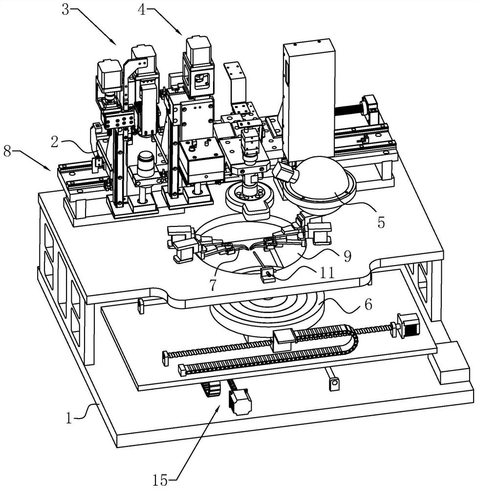
[0028] A light-emitting device test one machine, such as figure 1 As shown, including the seat 1, the seat 1 includes a first side surface and a second table surface spaced between the first table, the area of ​​the first side surface is greater than the area of ​​the second side, and the first side surface is located directly below the second side. . Among them, the second platform has a gap 9 that penetrates its upper and lower surfaces, allowing the gap 9 to be circulated; the second plan is located at a space 9 installed four test needles 7 and blowing parts 11, four tests The needle 7 is bent down and is close to the center of the gap 9, and the air blowing port of the blowing member 11 is toward the tip of the test needle 7; there is a slide table 6, which is located between the first side and the second side surface. The tablet 6 is used to carry the measure...


PUM


Abstract

The invention discloses an all-in-one machine for testing light-emitting devices, which includes a machine base and a mounting base. The mounting base is sequentially provided with a near-field testing component for testing the beam waist radius of a light-emitting component along its length direction, and a test component for testing the divergence angle of a light-emitting component. The far-field test assembly and the integrating sphere used to test the wavelength brightness of the light-emitting element, the base is equipped with a slide table for carrying the light-emitting element, a test needle for contacting with the electrode of the light-emitting element, and a test needle for driving the light-emitting element. The first driving mechanism for the mounting base to move along its length direction, after installing the light-emitting element on the slide table, make the electrode of the light-emitting element contact the test needle, and the first driving mechanism drives the mounting base on the machine base along the length direction of the mounting base Move so that the near-field test component, the far-field test component and the integrating sphere are testing the light-emitting parts on the carrier table respectively, so as to test various light parameters of the light-emitting parts; according to the light parameter test types of the light-emitting parts, Different test components are installed sequentially on the mounting base, saving time and effort.

Description

Technical field [0001] The present invention relates to the field of light-emitting part detection, and more particularly, it relates to a light-emitting device test one machine. Background technique [0002] In the existing light-emitting part test system, by testing the corresponding electrode corresponding to the light collecting member, the corresponding current is applied, and the light parameters are detected, and the test of the light parameters includes several critical parameters, such as optical power. Wavelength, far field divergence angle, near field spot, near-field waist radius, etc. [0003] The slide table in the light-emitting part test system is used to carry the measured light, and the photometry test device is used to collect light parameters of the light-emitting surface when the measured light is turned on, and the light parameters of the light collector require different light parameter test devices. Test, in the prior art, the measured light is installed u...

Claims


Application Information

Patent Timeline
Patent Type & Authority Patents(China)
IPC IPC(8): G01M11/02
CPCG01M11/00
Inventor 刘振辉王业文颜华江杨波
Owner SHENZHEN SIDEA SEMICON EQUIP
Features
  • R&D
  • Intellectual Property
  • Life Sciences
  • Materials
  • Tech Scout
  • Unparalleled Data Quality
  • Higher Quality Content
  • 60% Fewer Hallucinations
Learn More