Locking device for switch cabinet transfer trolley

A locking device and switchgear technology, applied in switchgear, pull-out switchgear, electrical components, etc., can solve problems such as slipping, decoupling of triangular lock tongue and switchgear, and inability to effectively lock transfer trolley and switchgear, etc. The effect of solving false blocking and improving reliability

Pending Publication Date: 2020-02-04
JIANGSU ELECTRIC POWER CO +1
View PDF0 Cites 0 Cited by
  • Summary
  • Abstract
  • Description
  • Claims
  • Application Information

AI Technical Summary

Problems solved by technology

[0003] The locking device of the existing switchgear transfer trolley has the following problems in use: First, whether the docking and locking operation lever reliably locks the transfer trolley and the switchgear and docks, completely depends on the experience and judgment of the operator, and due to negligence, etc. The reason is that it is easy for the transfer trolley to perform a locking operation when it is not close to the switch cabinet, resulting in the triangular lock tongue that is docked with the locking operating lever not actually locking the transfer trolley and the switch cabinet; second, it is prone to occur during the operation The triangular lock tongue at the rear end is decoupled from the switchgear due to accidentally touching the operating handle at the front end of the docking locking operating lever. The above two situations will cause the transfer trolley and the switchgear to be unable to be effectively locked. In the process of pulling the high-voltage handcart circuit breaker from the switchgear to the transfer trolley when the trolley and the switchgear are not effectively locked, the high-voltage handcart circuit breaker may fall to the ground, which is harmful to the personal safety belt of the equipment and operators. to threaten
Third, after the high-voltage handcart circuit breaker is placed on the transfer trolley, during the movement of the transfer trolley, only two points at the front end of the high-voltage handcart circuit breaker are fixed, and the rear end of the high-voltage handcart circuit breaker has no fixing or limiting mechanism. If the tightening device falls off during the transfer process due to improper operation, there is a risk that the high-voltage handcart circuit breaker will slip from the support platform of the transfer trolley

Method used


Image

  • Locking device for switch cabinet transfer trolley
  • Locking device for switch cabinet transfer trolley
  • Locking device for switch cabinet transfer trolley

Examples


Embodiment 1)

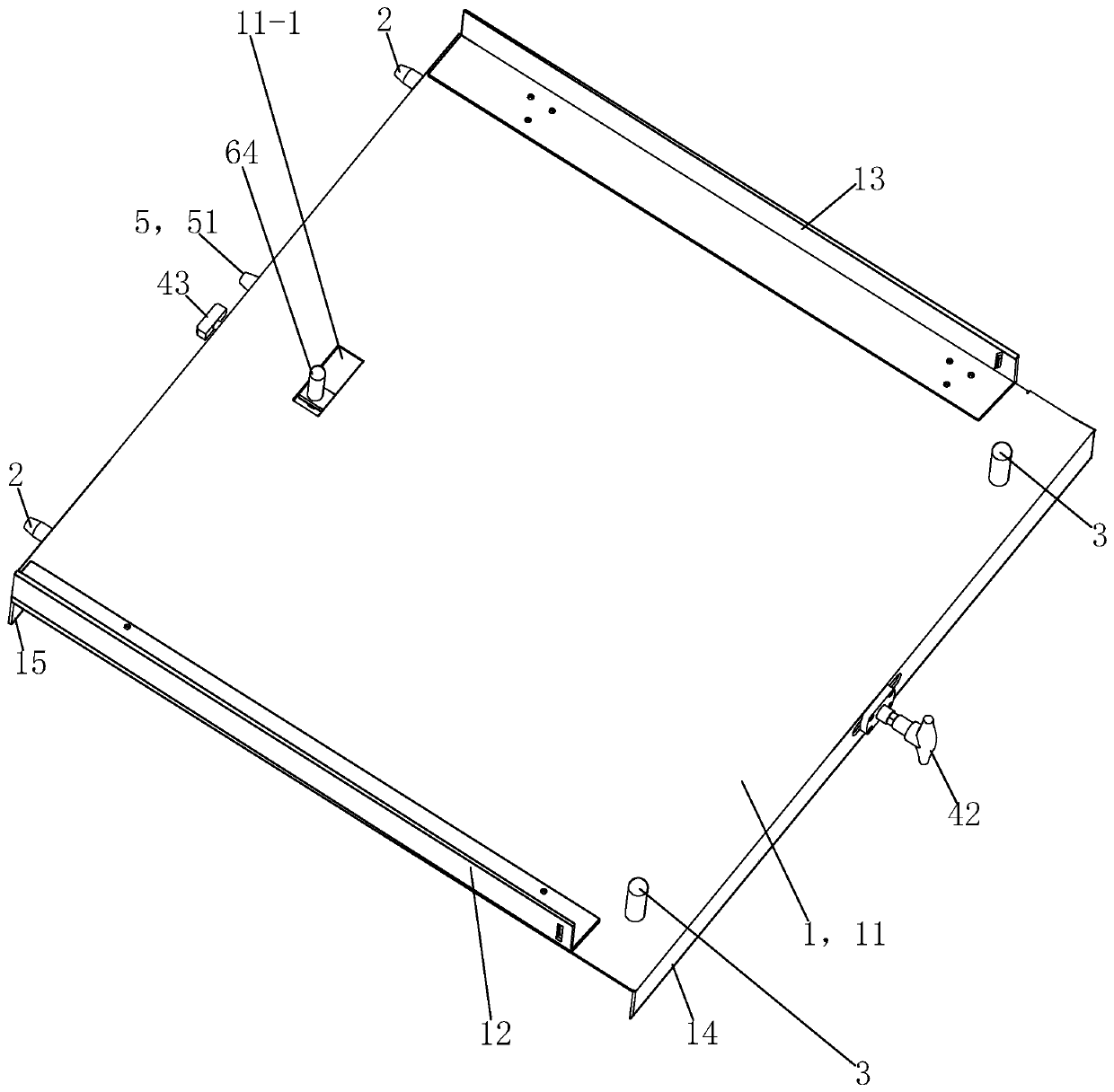
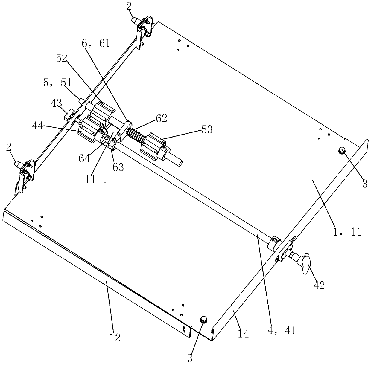
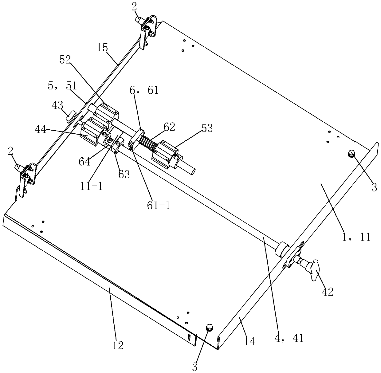
[0025] See figure 1 with figure 2 , The locking device of the switch cabinet transfer trolley in this embodiment is mainly composed of a supporting platform 1, a positioning pin 2, a limit fixing column 3, a docking and locking operating lever 4, a close identification component 5 and a self-locking component 6.

[0026]The support platform 1 is used as the installation base of the locking device for the switchgear transfer trolley in this embodiment. The support platform 1 is mainly composed of a panel 11 , a left limiting member 12 , a right limiting member 13 , a front mounting plate 14 and a rear mounting plate 15 . The panel 11 is a square plate body, and the panel 11 is provided with a rectangular slot in the middle of the rear part as a blocking column to give way to the slot 11 - 1 . The left limiter 12 and the right limiter 13 are L-shaped plate parts in the longitudinal section, and the left limiter 12 and the right limiter 13 are fixedly arranged as mirror images...


PUM


Abstract

The invention provides a locking device for a switch cabinet transfer trolley. The locking device comprises a supporting platform serving as a mounting foundation, two positioning pins fixedly arranged on two sides of the rear end of the supporting platform, two limiting fixed columns fixedly arranged on the front side of the upper end surface of the supporting platform, and a butt-joint locking operation rod which is fixedly arranged on the supporting platform and is used for locking the switch cabinet transfer trolley and the switch cabinet in a butt-joint manner through rotation during use.The locking device is structurally characterized by further comprising a tight attachment identification assembly and a self-locking assembly, wherein the tight attachment identification assembly isfixedly arranged on the supporting platform and used for judging whether the switch cabinet transfer trolley is tightly attached to the switch cabinet or not during use, and the self-locking assemblyis used for locking the butt-joint locking operation rod when the switch cabinet transfer trolley is not tightly attached to the switch cabinet during use. Through the structural design, the switch cabinet transfer trolley can be effectively ensured to be tightly locked and butted with the switch cabinet in use, and a high-voltage handcart circuit breaker can be effectively prevented from slidingoff from the rear part of a supporting platform of the transfer trolley in the transfer process.

Description

technical field [0001] The invention relates to an auxiliary tool for a substation switch cabinet maintenance device, in particular to a locking device for a switch cabinet transfer trolley. Background technique [0002] The switchgear transfer trolley is an important auxiliary tool for pulling the high-voltage handcart circuit breaker of the substation out of the armored cabinet and transferring it to a suitable place for electrical testing and maintenance. The existing substation high-voltage switch transfer trolley is mainly composed of a car body, four rollers located at the four corners below the car body, a support platform located above the car body, and a wheel set between the car body and the support platform to adjust the height of the support platform. The height adjustment device, and the locking device on the support platform for docking with the switch cabinet and fixing the high-voltage handcart circuit breaker during the transfer process, among which the lock...

Claims


Application Information

Patent Timeline
Patent Type & Authority Applications(China)
IPC IPC(8): H02B11/133H02B11/167
CPCH02B11/133H02B11/167
Inventor 褚国伟袁磊朱文明崔绍军
Owner JIANGSU ELECTRIC POWER CO
Why Eureka
Try Eureka