Magnetic clutch coupler

A coupling and magnetic technology, applied in the field of magnetic clutch coupling, can solve problems such as single function, and achieve the effect of perfect function and small wear

Inactive Publication Date: 2020-02-04
BEIJING HONGHUI INT ENERGY TECH DEV CO LTD
View PDF10 Cites 3 Cited by
  • Summary
  • Abstract
  • Description
  • Claims
  • Application Information

AI Technical Summary

Problems solved by technology

[0004] The purpose of the present invention is to provide a magnetic clutch coupling to alleviate the single-function technical problem of the magnetic drive coupling in the prior art

Method used


Image

  • Magnetic clutch coupler
  • Magnetic clutch coupler
  • Magnetic clutch coupler

Examples


Embodiment Construction

[0045] The technical solutions of the present invention will be clearly and completely described below in conjunction with the accompanying drawings. Apparently, the described embodiments are some of the embodiments of the present invention, but not all of them. Based on the embodiments of the present invention, all other embodiments obtained by persons of ordinary skill in the art without making creative efforts belong to the protection scope of the present invention.

[0046]In the description of the present invention, it should be noted that the orientations or positional relationships indicated by the terms "center", "inner" and "outer" are based on the orientations or positional relationships shown in the drawings, and are only for the convenience of describing the present invention and simplified descriptions, rather than indicating or implying that the device or element referred to must have a specific orientation, be constructed and operate in a specific orientation, an...


PUM


Abstract

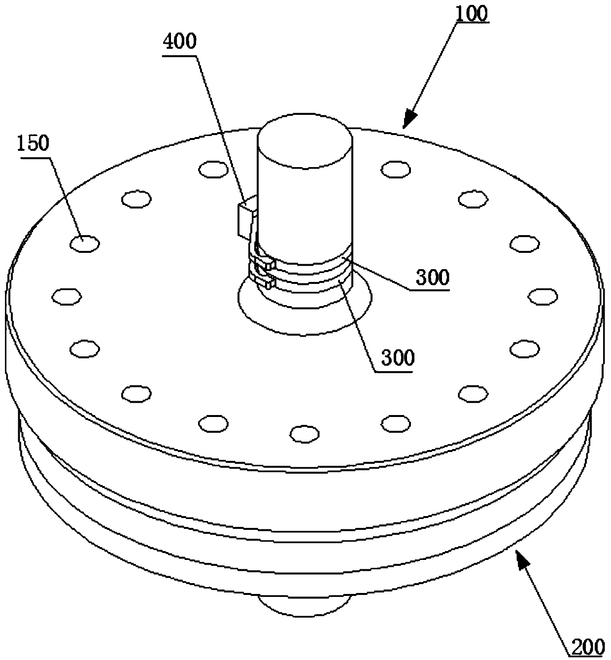
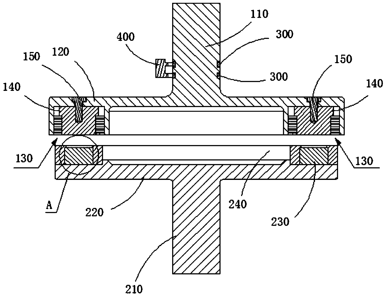
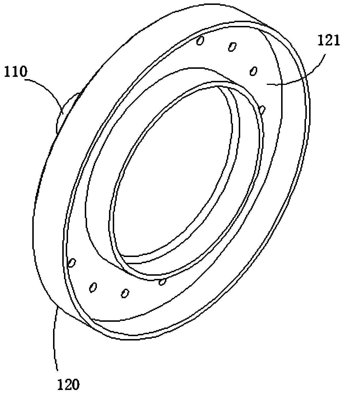
The invention relates to the technical field of magnetic force transmission equipment, in particular to a magnetic clutch coupler. The magnetic clutch coupler comprises a first connection assembly anda second connection assembly, wherein a gap exists between the first connection assembly and the second connection assembly, the first connection assembly comprises a first connection shaft and a first magnetic piece which are fixed relative to each other, the second connection assembly comprises a second connection shaft and a second magnetic piece which are fixed to each other, the first connection shaft and the second connection shaft are coaxially arranged, the first magnetic piece and the second magnetic piece are arranged opposite to each other, the first magnetic piece and/or the second magnetic piece is an electromagnet, and the second connection assembly can be driven to rotate by the first connection assembly under a magnetic force effect when the electromagnet is energized. With the magnetic clutch coupler provided by the invention, a transmission function can be achieved, the clutch function also can be achieved, the function is more perfect, and the magnetic clutch coupler is relatively low in abrasion and low in energy loss.

Description

technical field [0001] The invention relates to the technical field of magnetic transmission equipment, in particular to a magnetic clutch shaft coupling. Background technique [0002] The magnetic transmission coupling generally includes a first permanent magnet set and a second permanent magnet set opposite to each other. The first permanent magnet set is connected to the drive shaft, and the second permanent magnet set is connected to the driven shaft. When the drive shaft rotates, it can Drive the first permanent magnet group to rotate as a whole. Under the action of magnetic force, the second permanent magnet group can follow the synchronous rotation of the first permanent magnet group, so that the transmission between the driving shaft and the driven shaft can be realized. However, the existing magnetic force The transmission coupling cannot realize the clutch between the driving shaft and the driven shaft, and has a single function. [0003] To sum up, how to overcom...

Claims


Application Information

Patent Timeline
Patent Type & Authority Applications(China)
IPC IPC(8): H02K49/10
CPCH02K49/102H02K49/108
Inventor 彭龙
Owner BEIJING HONGHUI INT ENERGY TECH DEV CO LTD
Why Eureka
Try Eureka