Telescopic pipeline flow energy capture device

A pipeline flow, energy harvester technology, applied in piezoelectric/electrostrictive or magnetostrictive motors, electrical components, generators/motors, etc., can solve the problem of limited battery life, economic loss, oil and gas pipeline leakage and other problems, to achieve the effect of effective frequency bandwidth, high reliability and strong power generation capacity

Active Publication Date: 2020-02-04
ZHEJIANG NORMAL UNIVERSITY
View PDF13 Cites 2 Cited by
  • Summary
  • Abstract
  • Description
  • Claims
  • Application Information

AI Technical Summary

Problems solved by technology

[0002] During the operation of oil and gas pipelines, due to natural corrosion, natural force majeure, especially man-made theft, oil and gas pipeline leakage incidents occur from time to time, which not only caused huge economic losses, but also caused serious pollution to the surrounding natural environment.
In the past, it was maintained by manual inspection methods, but because the pipeline laying distance is long, and it is often in an inaccessible or inconvenient place, it is difficult to detect leakage in time and repair i

Method used


Image

  • Telescopic pipeline flow energy capture device
  • Telescopic pipeline flow energy capture device
  • Telescopic pipeline flow energy capture device

Examples


Embodiment Construction

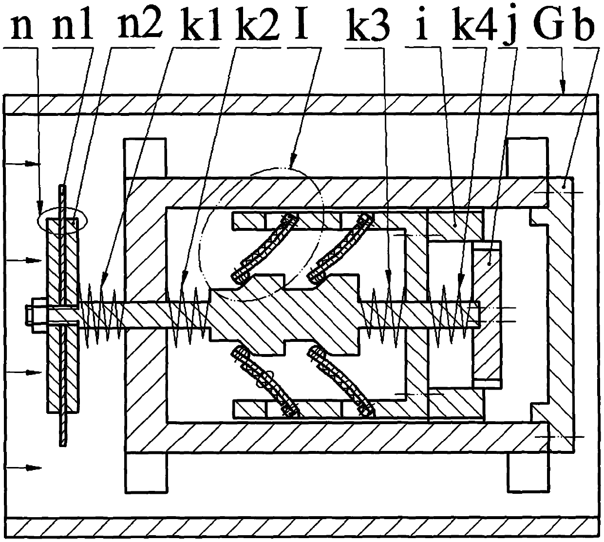
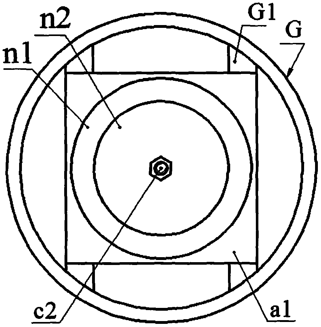
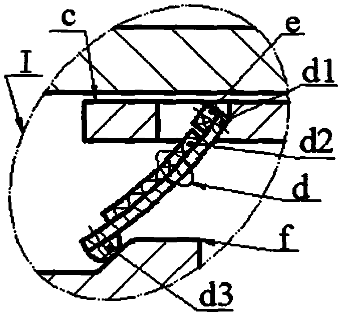
[0013] On the inner wall of the pipe G, a shell a is installed through the radial plate G1, and the end of the side wall a2 of the shell a is installed with an end cover b through screws; the center of the vertical plate c1 of the bracket c is provided with an inner pin hole c2, and the upper and lower sides of the same side Both ends are provided with a horizontal plate c4, and the horizontal plate c4 is provided with an inclined installation surface c5, the installation surface c5 is located on the wall of the hole on the horizontal plate c4, and the acute angle c6 formed by the installation surface c5 and the horizontal plate c4 is the installation angle. The installation angle is greater than 30 degrees; the left and right ends of the actuator f are respectively provided with a left pin f4 and a right pin f7, the left pin f4 and the right pin f7 are coaxial, and the upper and lower sides of the actuator f are along the left pin f4 and the right pin f7 There are multiple cam...


PUM


Abstract

The invention relates to a telescopic pipeline flow energy capture device, and belongs to the technical field of new energy and pipeline monitoring. A shell is installed in a pipeline, and an end cover is installed at the end part of a side wall of the shell; an inner pin hole is formed in the center of a vertical plate of a bracket, and horizontal plates with inclined mounting surfaces are arranged at the upper and lower ends on the same side of the vertical plate; left and right pins are respectively arranged on the left and right sides of an exciter, a plurality of cams are arranged on theupper and lower side along the axial direction of the left and right pins, and a cam surface is composed of a bottom surface, an inclined surface and a top surface, which are connected in sequence; the exciter is placed in the shell, the left pin extends out from the bottom wall of the shell, and a blunt body is installed on the end part of the left pin; a supporting spring and a buffer spring arerespectively arranged on the left pins on the left and right sides of the bottom wall of the shell in a sleeving manner; the vertical plate of the bracket is installed on the right pin through the inner pin hole, and a left spring and a right spring are respectively arranged on the right pins on the left and right sides of the vertical plate; and one end of a piezoelectric vibrator is installed on the mounting surface of the bracket, the piezoelectric vibrator is a cantilever beam structure formed by bonding a substrate with a piezoelectric sheet, a top block at a free end of the piezoelectric vibrator abuts against the cam surface, the top block is in contact with the midpoint of the inclined surface of the cam when it is not working.

Description

technical field [0001] The invention belongs to the technical field of new energy and oil and gas pipeline monitoring systems, and in particular relates to a telescopic pipeline flow energy harvester. Background technique [0002] During the operation of oil and gas pipelines, oil and gas pipeline leakage incidents occur frequently due to natural corrosion, force majeure of nature, especially man-made theft, which not only caused huge economic losses, but also caused serious pollution to the surrounding natural environment. In the past, it was maintained by manual inspection methods, but because the pipeline laying distance is long, and it is often in an inaccessible or inconvenient place, it is difficult to detect leakage in time and repair it in time, so people have proposed various types of pipeline leakage monitoring or anti-theft systems. , some technologies are relatively mature; but the power supply problem of the oil and gas pipeline monitoring system has not been we...

Claims


Application Information

Patent Timeline
IPC IPC(8): H02N2/18
CPCH02N2/185H02N2/186
Inventor 王淑云柴超辉万嫩郑佳佳廖卫林陈松黄芳胜曾平
Owner ZHEJIANG NORMAL UNIVERSITY
Why Eureka
Try Eureka