Magnetic yoke body of induction heating furnace
A technology of induction heating furnace and yoke, which is applied in the direction of induction heating and coil device, can solve the problems of high production cost and complex structure of induction heating furnace, and achieve the effect of reducing the secondary consumption of electric power and reducing power consumption
- Summary
- Abstract
- Description
- Claims
- Application Information
AI Technical Summary
Problems solved by technology
Method used
Image
Examples
Embodiment 1
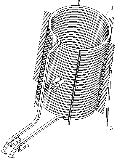
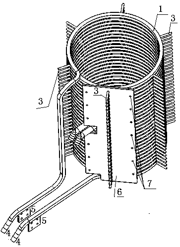
[0055] Such as Figure 7 As shown, in this embodiment, the yoke unit body is a column-type fixed combined flat plate structure, and the yoke unit body has an outer fixing plate 13 for clamping the yoke element 8, a magnet The inner fixed plate 6 of the yoke element; the combination of the inner fixed plate 6 of the yoke element and the induction coil 1 is as follows: figure 2 Shown; induction coil 1 as figure 1 shown.
[0056] The center of the inner fixing plate 6 of the yoke element has a row of fixing holes 7 cooperating with the fastening bolts 3 on the induction coil; The fixing holes 7, the row of fixing holes 7 on both sides are two rows symmetrically arranged;
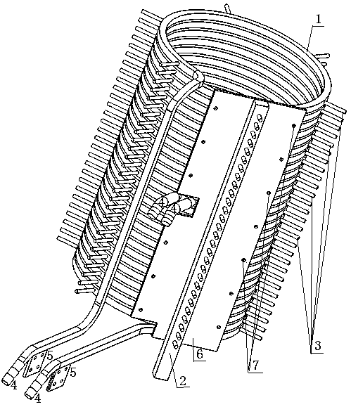
[0057] combine image 3 , the supporting and fixing column 2 is located in the middle of the inner fixing plate 6 of the yoke element, and the supporting and fixing column 2 is fixedly connected with the induction coil 1 through the fixing bolt 3 fixed on the induction coil 1; There are a plurality of thr...
Embodiment 2
[0068] Figure 16 A schematic structural diagram of Embodiment 2 of the present invention is given. The main structure of this embodiment is the same as that of Embodiment 1. In this embodiment, the yoke unit body is a flat yoke structure fixed between columns, and the yoke unit multiple bodies; combined Figure 11 , each yoke unit body includes a yoke element outer fixing plate 13 and a yoke element inner fixing plate 6 for clamping the yoke element 8; the yoke element outer fixing plate and the yoke element inner fixing plate will The yoke elements 8 are sandwiched in one piece and arranged uniformly along the periphery of the induction coil 1 .
[0069] combine Figure 8 , the fixed plate 6 inside the yoke element has a fixed hole 7 for passing through the fastening screw 10; the fixed holes 7 are arranged in two rows symmetrically; the upper end of the fixed plate 6 inside the yoke element , the lower end and the middle part are respectively designed with reserved openi...
Embodiment 3
[0083] Figure 19 A schematic structural diagram of Embodiment 3 of the present invention is given. In this embodiment, the yoke unit body is a fixed arc structure between columns, combined with Figure 17 As shown, the yoke element 8 is an arc-shaped plate structure; the yoke element 8 is arranged around the periphery of the induction coil 1; the supporting connection mechanism has a supporting fixed column 2 and a pressing plate 15; the described The supporting and fixing columns 2 are arranged between every two adjacent yoke elements 8;
[0084]After the arc-shaped yoke element is placed in place, the outer end surface of the supporting and fixing column 2 is an arc shape matching the arc shape of the yoke element 8, and the inner wall surface is an arc-shaped pressure plate 15 and bolts, and the The yoke element 8 on both sides of the supporting column 2 is fixedly connected with the induction coil 1; the structure of the pressing plate 15 is as follows: Figure 18 As sh...
PUM
 Abstract
Description
Claims
Application Information
 - R&D Engineer
- R&D Manager
- IP Professional
- Industry Leading Data Capabilities
- Powerful AI technology
- Patent DNA Extraction
Browse by: Latest US Patents, China's latest patents, Technical Efficacy Thesaurus, Application Domain, Technology Topic, Popular Technical Reports.
© 2024 PatSnap. All rights reserved.Legal|Privacy policy|Modern Slavery Act Transparency Statement|Sitemap|About US| Contact US: help@patsnap.com


