Eureka AIR delivers breakthrough ideas for toughest innovation challenges, trusted by R&D personnel around the world.

Antenna microgravity simulation system

A microgravity simulation and antenna technology, which is applied in the simulation devices of space navigation conditions, space navigation equipment, transportation and packaging, etc. Not good and other problems, to achieve a good effect of universality

Inactive Publication Date: 2020-02-07
BEIJING INSTITUTE OF TECHNOLOGYGY
View PDF4 Cites 6 Cited by
  • Summary
  • Abstract
  • Description
  • Claims
  • Application Information

AI Technical Summary

Problems solved by technology

However, the structure and movement of the antenna are relatively complex, and the size range is also large. When performing ground microgravity simulation experiments, the gravity unloaded counterweight of the existing antenna microgravity simulation device can only move along the fixed guide rail, and the movement of the antenna The process control is relatively complicated, and the accuracy of gravity unloading is not high
In addition, the universality of existing antenna microgravity simulation devices is not good. Usually, a system can only unload gravity for one type of antenna, etc. There are many problems that have not been well solved. Therefore, the microgravity simulation of antennas The device has higher requirements

Method used


Image

  • Antenna microgravity simulation system
  • Antenna microgravity simulation system
  • Antenna microgravity simulation system

Examples


Embodiment 1

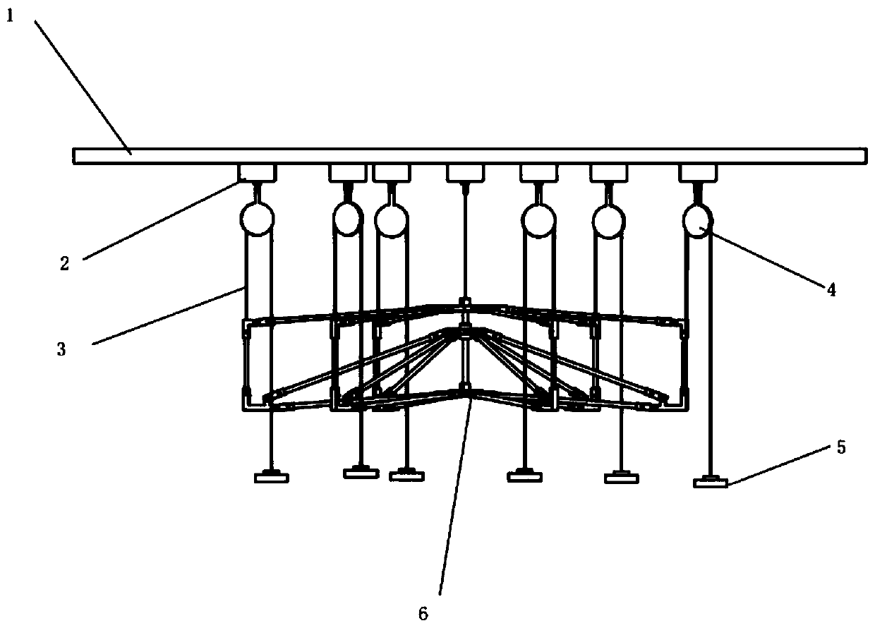
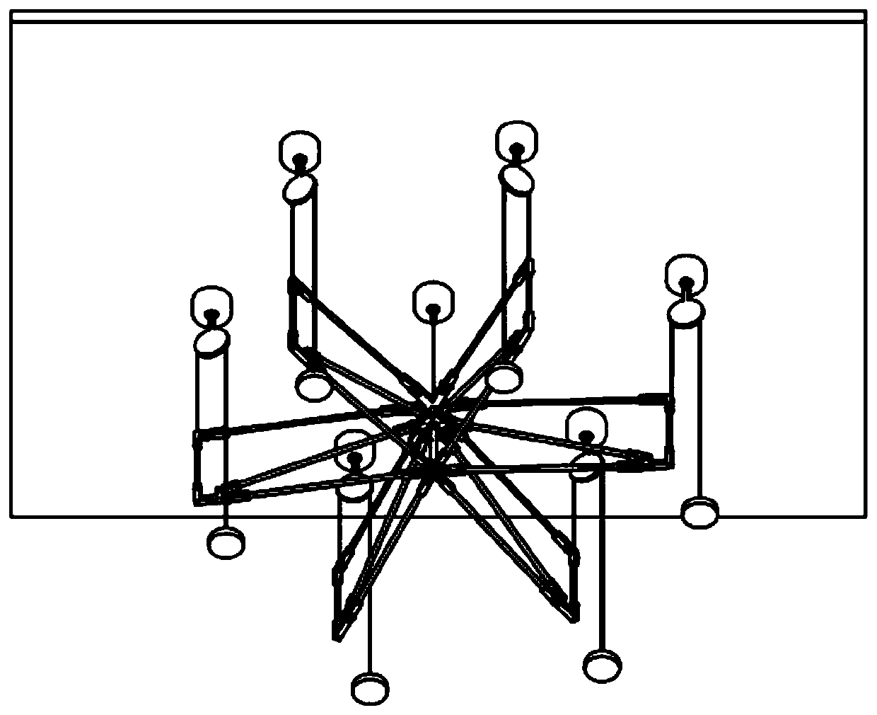
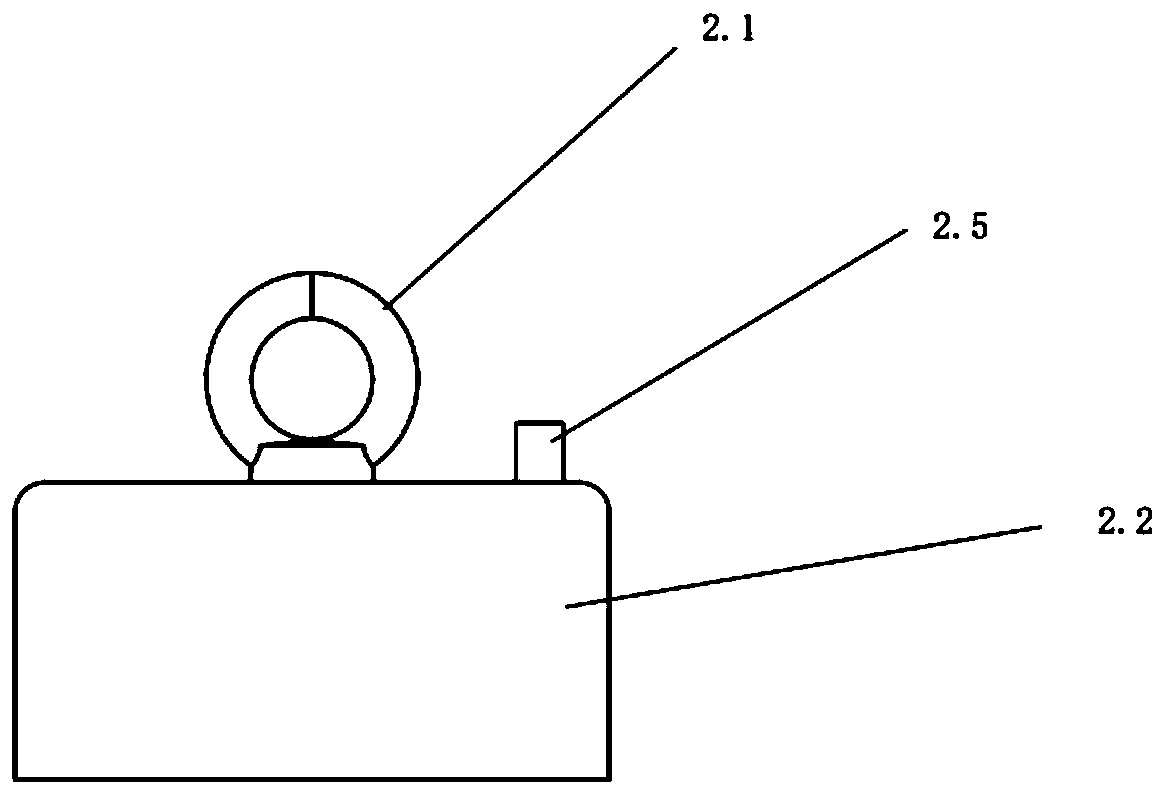
[0031] Such as figure 1 , figure 2 , image 3 and Figure 4As shown, the antenna microgravity simulation system disclosed in this embodiment includes a magnetic levitation board 1 , a magnetic levitation air foot 2 , a suspension rope 3 , a pulley 4 , a counterweight 5 , and an antenna 6 . The ground microgravity simulation experiment object is the antenna 6. The counterweight 5 is used for gravitational unloading of the antenna. The magnetic levitation board 1 and the magnetic levitation air foot 2 generate magnetic attraction for making the magnetic levitation air foot 2 adsorb on the surface of the magnetic levitation board 1 . When the high-pressure gas enters the magnetic levitation air base 2, the high-pressure gas film generated at the bottom of the magnetic levitation air base 2 and the surface of the magnetic levitation plate 1 makes the magnetic levitation air base 2 eliminate friction and realize suspension, so that the magnetic levitation air base 2 can move a...


PUM


Abstract

The invention discloses an antenna microgravity simulation system, and belongs to the field of antenna microgravity simulation. The antenna microgravity simulation system comprises a magnetic levitation plate, magnetic levitation air feet, lifting ropes, pulleys, balancing weights and an antenna. The ground microgravity simulation experimental subject is the antenna. The balancing weights are usedfor unloading the gravity of the antenna. The magnetic levitation plate and the magnetic levitation air feet are used for generating magnetic attraction force for enabling the magnetic levitation airfeet to be adsorbed on the surface of the magnetic levitation plate. A magnetic air-suspending hoisting device is adopted, the balancing blocks for unloading the gravity can move in any direction ofthe surface of the magnetic levitation plate in a follow-up manner according to the unfolding and folding motion state of the antenna and does not move along a fixed guide rail, and gravity unloadingon the whole antenna structure is completed; and the gravity unloading precision is high, and the microgravity simulation effect is closer to the true state of the ontrack work of the antenna. The antenna microgravity simulation system can meet the antenna microgravity simulation requirements of different numbers of gravity unloading points and different gravity unloading positions, can adapt to antennae of different sizes and is good in universality.

Description

technical field [0001] The invention relates to an antenna microgravity simulation system, in particular to a high-precision microgravity simulation system for various types of space antennas in arbitrarily unfolding and retracting motion states, and belongs to the field of antenna microgravity simulation. Background technique [0002] With the continuous development of aerospace technology, various large-scale space deployable antennas are more and more widely used. At present, the suspension rope method is commonly used in domestic ground microgravity simulation experiments for antennas. Its principle is to hang the antenna through a flexible cable, so that the tension of the flexible cable is always equal to the gravity of the structure, so as to realize the unloading of the gravity of the object. . At present, the rope method is divided into two types: active gravity balance method and passive gravity balance method. With the high-efficiency and high-precision requirem...

Claims


Application Information

Patent Timeline
IPC IPC(8): B64G7/00
CPCB64G7/00
Inventor 宋晓东施建才宣佳珺孙志成
Owner BEIJING INSTITUTE OF TECHNOLOGYGY
Why Eureka
Eureka Blog
Learn More