Automatic permanent magnet lifter

A permanent magnet lifter and lifter technology, which is applied in the direction of load hanging components, transportation and packaging, etc., can solve the problems of inconvenient operation, affecting lifting work efficiency, and high safety factor, so as to reduce personnel operation steps and improve The effect of lifting work efficiency

Active Publication Date: 2020-02-07
XUZHOU OUBAI RUI INTELLIGENT EQUIP CO LTD
View PDF7 Cites 2 Cited by
  • Summary
  • Abstract
  • Description
  • Claims
  • Application Information

AI Technical Summary

Problems solved by technology

[0002] The permanent magnet lifter, also known as the permanent magnet lifter, has the characteristics of small size, strong holding force, no electricity, almost zero residual magnetism, and high safety factor. Most of the permanent magnet lifters currently used are manual. Start the switch, and the personnel rotate the remote lever on the jack to drive the internal moving magnet to rotate, and cooperate with the fixed magnet to form an attractive magnetic field, but the handle of this hand-operated permanent magnet jack is easy to cause a shock The accidental closing of the heavy equipment caused the occurrence of lifting accidents. Although the limit column was used to fix the position of the remote rod, it needs to be controlled by personnel every time when it is used. The lifting operation method is inconvenient and affects the efficiency of lifting work.
[0003] The notification number CN206427906U discloses a safe permanent magnet crane, including a crane outer shell, a lifting hook is arranged above the crane outer shell, and a crane hook fixing plate is provided at the connection position between the crane outer shell and the lifting hook, A moving magnet rotating shaft is arranged at the inner middle position of the outer casing of the crane, and a lifting suction cup is arranged below the outer casing of the crane, and a fixed magnet N pole is arranged at one end above the inner upper end of the moving magnet rotating shaft, and a fixed magnet is arranged at the other end. The S pole of the magnet, the rotating handle of the crane lacks the structure to fix the handle, and the handle is easy to be bumped and rotated during lifting, causing the permanent magnetic lifting magnetic closure to disappear, resulting in a greater safety hazard
[0004] Notification number CN206427907U discloses a kind of hand rod retractable permanent magnet lifter specially used for lifting, including a jack housing, a hand rod limit bolt and a ring fixing mounting frame, and one side of the jack housing is provided with A movable magnet connection head, a telescopic rod installation sleeve is arranged above the movable magnet connection head, the hand lever limit bolt is installed on the telescopic rod installation sleeve, and a magnet is embedded above the telescopic rod installation sleeve Rotate the threaded hand lever, the side of the lifter shell close to the movable magnet connector is provided with a hand lever limit hole, and the inside of the lifter shell is provided with a rotating permanent magnet below the inside of the lifter shell, the inside of the lifter shell A fixed permanent magnet is arranged near the top of the rotating permanent magnet, and permanent magnet fixing buckles are arranged in the inside of the jack housing near the two ends of the fixed permanent magnet. The lever is accidentally closed due to collision. When operating the limit, the personnel need to unscrew the limit bolt. At the same time, when using the hand lever, the limit bolt needs to be disassembled again. The operation is inconvenient and time-consuming

Method used


Image

  • Automatic permanent magnet lifter
  • Automatic permanent magnet lifter
  • Automatic permanent magnet lifter

Examples


Embodiment 1

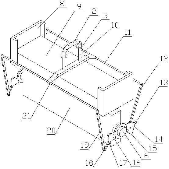
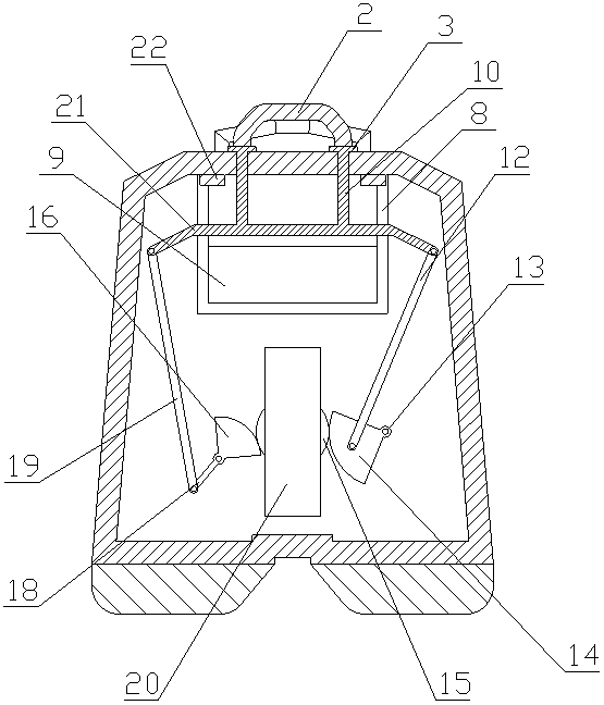
[0021] An automatic permanent magnet jack of the present invention is realized as follows: an automatic permanent magnet jack of the present invention is composed of a main device and a magnetic adsorption device, and the main device is composed of a jack shell (1), a lifting ring (4) ), a bottom suction cup (7) and an elastic block (22). The bottom suction cup (7) is placed at the bottom of the jack shell (1), and the two lifting rings (4) are symmetrically placed on the jack shell (1). ), an elastic block (22) is placed on the inner surface of the top end of the jack housing (1), the elastic block (22) corresponds to the lifting frame (21), and the elastic block (22) It is a rubber block, preferably two elastic blocks (22), and the magnetic adsorption device consists of a sliding ring (2), a limit ring (3), a bearing (5), a rotating shaft (6), a fixed seat (8), Fixed magnet (9), slide bar (10), cross bar (11), No. 1 connecting rod (12), No. 1 fixed column (13), No. 1 sector ...

Embodiment 2

[0024] The difference between this embodiment and Embodiment 1 is that a spring (23) is added on the sliding rod (10), and the spring (23) is located between the top of the jack housing (1) and the lifting frame (21); using When it is convenient for the permanent magnet jack to put down the object, the inner lifting frame (21) of the jack is reset downward under the action of the spring (23) so that the rotating shaft (6) of the moving magnet (20) is rotated and reset to close the suction magnetic field;

[0025] Example 2:

[0026] The difference between this embodiment and Embodiment 1 is that the No. 1 gear and the No. 2 gear are replaced by the No. 4 gear (26) as a whole, and the No. 1 connecting rod (12) and the No. 2 connecting rod (19) are replaced as a whole with Straight toothed racks (24), one end of the two straight toothed racks (24) is hinged with two ends of the cross bar (11) respectively, and the other end of the straight toothed racks (24) extends vertically d...


PUM


Abstract

The invention discloses an automatic permanent magnet lifter. According to the automatic permanent magnet lifter, a sliding lifting ring is lifted so that two sector fans can be matched to rotate a third gear so as to rotate a movable magnet, and therefore a suction magnetic field can be formed for adsorbing an object and lift the object. The automatic permanent magnet lifter is characterized in that a bottom sucker is arranged at the bottom of a lifter shell; two lifting rings are symmetrically arranged on the top of the lifter shell; elastic blocks are arranged on the inner side face of thetop end of the lifter shell; the elastic blocks correspond to the lifting frame and are rubber blocks; the number of the elastic blocks is preferably two; a rotating shaft is arranged in the lifter shell, and the two ends of the rotating shaft are arranged at the two ends of the lifter shell through bearings correspondingly; the movable magnet is fixedly arranged on the rotating shaft in a sleeving manner; a fixed magnet is arranged over the movable magnet and is horizontally placed; two fixing seats are fixedly arranged at the two ends of the fixed magnet correspondingly; the tops of the fixing seats are connected with the upper inner side face of the lifter shell; and the lifting frame is arranged in the lifter shell and is located above the fixed magnet.

Description

technical field [0001] The invention relates to an automatic permanent magnet lifter, which relates to a lifter for adsorbing and hoisting a magnetically conductive object when an object is transported, and belongs to the field of mechanical equipment. In particular, it relates to an automatic permanent magnet lifter that pulls the sliding ring to make the two sector gears cooperate to rotate the third gear to rotate the moving magnet, thereby forming a suction magnetic field to attract objects for lifting. Background technique [0002] The permanent magnet lifter, also known as the permanent magnet suction lifter, has the characteristics of small size, strong holding force, no electricity, almost zero residual magnetism, and high safety factor. Most of the permanent magnet lifters currently used are manual control type. Start the switch, the personnel rotate the remote lever on the jack to drive the internal moving magnet to rotate, and cooperate with the fixed magnet to fo...

Claims


Application Information

Patent Timeline
Patent Type & Authority Applications(China)
IPC IPC(8): B66C1/04
CPCB66C1/04
Inventor 不公告发明人
Owner XUZHOU OUBAI RUI INTELLIGENT EQUIP CO LTD
Why Eureka
Try Eureka