A cotton cleaning device for textile
A technology of cotton cleaning and movable installation, which is applied in the direction of opening and cleaning with stirring arms and fiber cleaning machines, etc. It can solve the problems of low opening efficiency and poor impurity removal effect, achieve full opening operation, easy falling, and improve efficiency Effect
- Summary
- Abstract
- Description
- Claims
- Application Information
AI Technical Summary
Problems solved by technology
Method used
Image

Examples
specific Embodiment approach 1
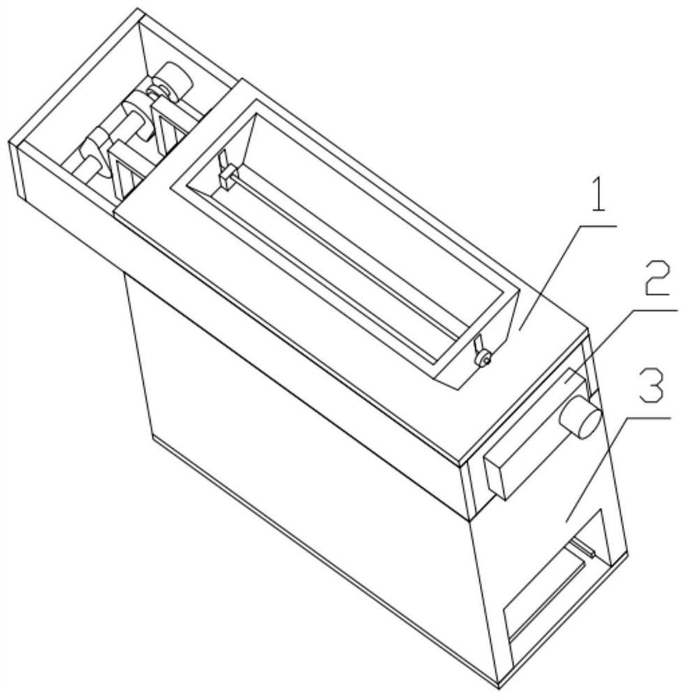
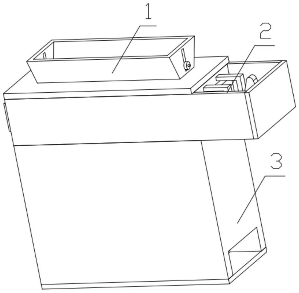
[0030] Combine below Figure 1-14 Describe this embodiment, a cotton cleaning device for textiles, including a top feeding mechanism 1, an opening mechanism 2 and a processing mechanism 3, the opening mechanism 2 is fixedly installed on the processing mechanism 3, and the top feeding mechanism 1 is fixed Installed on the opening mechanism 2.
specific Embodiment approach 2
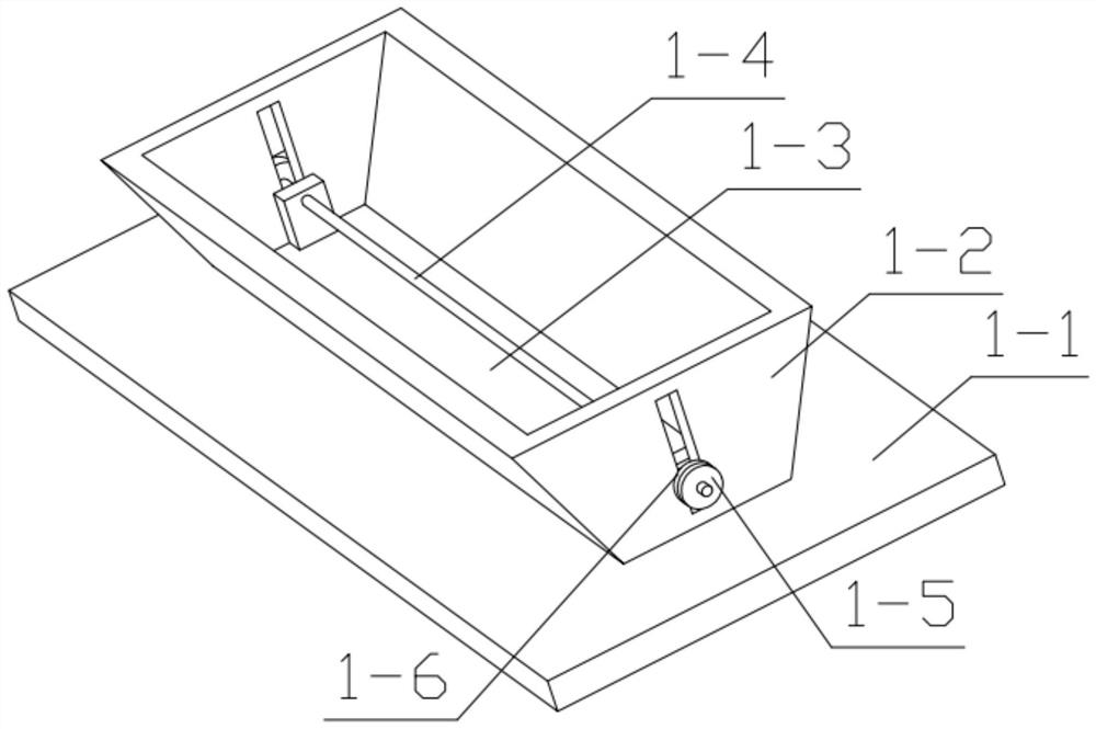
[0031] Combine below Figure 1-14 Describe this embodiment, this embodiment will further explain the first embodiment, the top feeding mechanism 1 includes a top cover plate 1-1, a wide mouth piece 1-2, a pressure plate 1-3, a threaded rod 1-4, a nut 1-5. The rubber ring piece 1-6, the wide mouth piece 1-2 is fixedly installed on the top cover plate 1-1, the rubber ring piece 1-6 is fixedly installed on the nut 1-5, and the nut 1-5 is connected with the threaded rod 1-4 threaded connection, the threaded rod 1-4 is movably installed on the through hole set on the wide-mouth piece 1-2, the threaded rod 1-4 is fixedly installed on the pressure plate 1-3, and the rubber ring 1-6 can increase the The effect of the friction force makes the positioning effect of the pressing plate 1-3 better, and the position of the pressing plate 1-3 is controlled by using the nut 1-5 and the rubber ring piece 1-6, which is convenient and easy to operate.
specific Embodiment approach 3
[0032] Combine below Figure 1-14Describe this embodiment, this embodiment will further explain the first embodiment, the opening mechanism 2 includes a connection frame 2-1, an intermittent adjustment assembly 2-2, an opening shaft assembly 2-3, and an opening motor 2-4 , Secondary shaft 2-5, the intermittent adjustment assembly 2-2 is installed on the connection frame 2-1, one end of the loosening shaft assembly 2-3 is installed on the intermittent adjustment assembly 2-2, and the other end is installed on the connection frame 2-1 above, the opening motor 2-4 is installed on the opening shaft assembly 2-3, the opening motor 2-4 is fixedly installed on the connection frame 2-1, and the opening shaft assembly 2-3 is engaged with the auxiliary shaft 2-5 , the unclamping shaft assembly 2-3 has the same structure as the auxiliary shaft 2-5; the intermittent adjustment assembly 2-2 includes a driving motor 2-2-1, positive cam 2-2-2, shaft rod 2-2-3, reverse Cam 2-2-4, small beari...
PUM
 Abstract
Description
Claims
Application Information
 - R&D
- Intellectual Property
- Life Sciences
- Materials
- Tech Scout
- Unparalleled Data Quality
- Higher Quality Content
- 60% Fewer Hallucinations
Browse by: Latest US Patents, China's latest patents, Technical Efficacy Thesaurus, Application Domain, Technology Topic, Popular Technical Reports.
© 2025 PatSnap. All rights reserved.Legal|Privacy policy|Modern Slavery Act Transparency Statement|Sitemap|About US| Contact US: help@patsnap.com