Eureka AIR delivers breakthrough ideas for toughest innovation challenges, trusted by R&D personnel around the world.
a high pole lamp
What is Al technical title?
Al technical title is built by PatSnap Al team. It summarizes the technical point description of the patent document.
A technology for high-pole lamps and lamp panels, which is applied in lighting auxiliary devices, lighting and heating equipment, fixed lighting devices, etc., and can solve problems such as poor heat dissipation, inability to quickly discharge heat, and reduced normal service life
Active Publication Date: 2021-05-04
YANGDE ELECTRIC GRP CO LTD
View PDF12 Cites 0 Cited by
Summary
Abstract
Description
Claims
Application Information
AI Technical Summary
This helps you quickly interpret patents by identifying the three key elements:
Problems solved by technology
Method used
Benefits of technology
Problems solved by technology
[0003] However, in the existing high pole lights, there are problems of inconvenient cleaning and maintenance, poor heat dissipation effect and weak practicability
In the long-term use process, it is difficult to replace the damaged light source, and it is difficult to remove dust from the lamp panel, which will affect the lighting effect; at the same time, during the lighting process, a large amount of heat generated cannot be quickly discharged, which is easy to damage the internal heating elements. impact, thereby reducing the normal service life; and low moisture resistance and intelligence
Method used
Image
Click on the blue label to locate the original text in one second.
Reading with bidirectional positioning of images and text.
Examples
Embodiment Construction
[0022] The following will clearly and completely describe the technical solutions in the embodiments of the present invention with reference to the accompanying drawings in the embodiments of the present invention. Obviously, the described embodiments are only some, not all, embodiments of the present invention. Based on the embodiments of the present invention, all other embodiments obtained by persons of ordinary skill in the art without making creative efforts belong to the protection scope of the present invention.
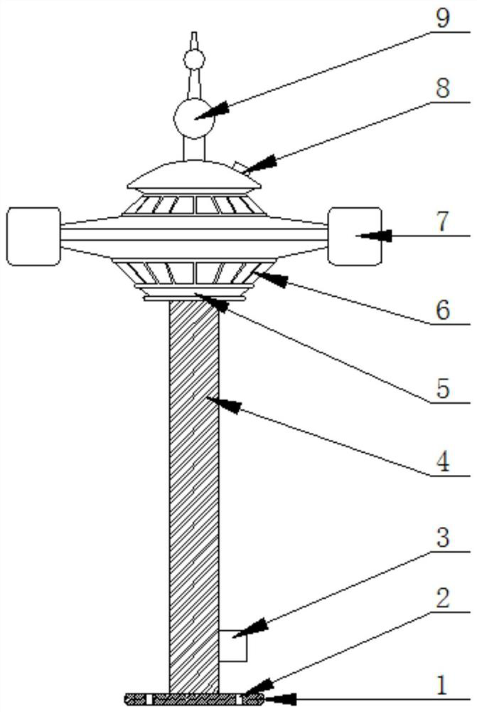
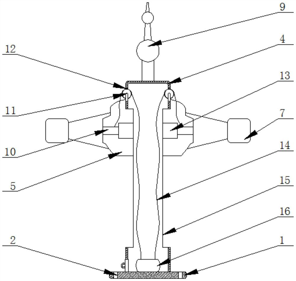
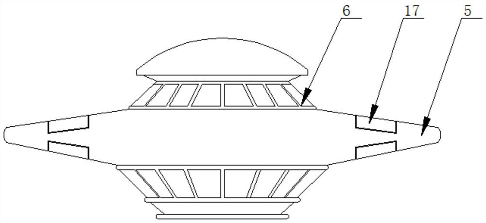
[0023] see Figure 1-8, the present invention provides a technical solution: a high pole lamp, including a bottom plate 1, bolt holes 2, a control box 3, a column 4, a lamp panel 5, an LED lamp panel 6, a cooling device 7, a photosensitive sensor 8, a lightning rod 9, Connecting column 10, fixed pulley 11, square mouth 12, slider 13, wire rope 14, chute 15, motor 16, dehumidification device 17, rotating shaft 18, baffle plate 19, alarm 20 and PLC controller 21...
PUM
Abstract
The invention discloses a high pole lamp, which comprises a bottom plate, a bolt hole, a control box, a column, a lamp panel, an LED lamp panel, a heat dissipation device, a photosensitive sensor, a lightning rod, a connecting column, a fixed pulley, a square mouth, a slider, a steel wire rope, Chute, motor, dehumidification device, rotating shaft, baffle plate, alarm and PLC controller, the top center of the column is fixed with a lightning rod by spot welding, the bottom of the column is fixed with a bottom plate by bolts, the bottom of the bottom plate Bolt holes are correspondingly opened on the outside, a motor is installed on the top side of the bottom plate, one side of the motor is movably connected to a rotating shaft through a coupling, one end of the rotating shaft is provided with a baffle plate, and one side of the column passes through A control box is fixed by bolts, an alarm and a PLC controller are installed inside the control box, and a chute is correspondingly provided on the outside of the column. features.
Description
technical field [0001] The invention relates to the technical field of lighting fixtures, in particular to a high pole lamp. Background technique [0002] High pole lights usually refer to a new type of lighting device composed of a steel tapered light pole over 15 meters and a high-power combined light stand. It is composed of lamp holder, internal lamp electrical, rod body and basic parts, and the shape of the lamp holder can be determined according to the user's requirements, the surrounding environment and the specific needs of lighting. The internal lamps are mostly composed of LED floodlights and LED floodlights, and the lighting radius can be Up to 60 meters. It has a wide range of applications, such as city squares, stations, docks, freight yards, highways, stadiums and overpasses. [0003] However, in the existing high pole lights, there are problems of inconvenient cleaning and maintenance, poor heat dissipation effect and weak practicability. In the long-term u...
Claims
Application Information
Patent Timeline
Application Date:The date an application was filed.
Publication Date:The date a patent or application was officially published.
First Publication Date:The earliest publication date of a patent with the same application number.
Issue Date:Publication date of the patent grant document.
PCT Entry Date:The Entry date of PCT National Phase.
Estimated Expiry Date:The statutory expiry date of a patent right according to the Patent Law, and it is the longest term of protection that the patent right can achieve without the termination of the patent right due to other reasons(Term extension factor has been taken into account ).
Invalid Date:Actual expiry date is based on effective date or publication date of legal transaction data of invalid patent.