
Tool for measuring angle of tapered hole at bottom of deep groove cavity

A technology of tapered holes and deep grooves, which is applied in the field of instruments for quickly measuring the angle of tapered holes at the bottom of deep grooves. It can solve the problems of high cost, difficulty in observing the scale line of plug gauges, and inability to read the specific value of hole taper.

Pending Publication Date: 2020-02-07
CHENGDU AIRCRAFT INDUSTRY GROUP
View PDF0 Cites 2 Cited by
  • Summary
  • Abstract
  • Description
  • Claims
  • Application Information

AI Technical Summary

Problems solved by technology

This detection method is costly, and it can only judge whether the taper of the hole meets the tolerance requirements, and cannot read the specific value of the taper of the hole
For the tapered hole at the bottom of the deep groove, it is difficult to observe the scale line on the plug gauge, and it is impossible to make an accurate judgment on whether the taper of the hole is qualified

Method used


Image

  • Tool for measuring angle of tapered hole at bottom of deep groove cavity
  • Tool for measuring angle of tapered hole at bottom of deep groove cavity
  • Tool for measuring angle of tapered hole at bottom of deep groove cavity

Examples


Embodiment 1

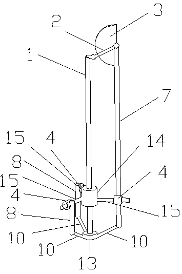
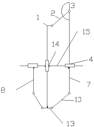
[0023] A tool for measuring the angle of a tapered hole at the bottom of a deep groove cavity includes a central rod 1, the top of which is connected to one end of a connecting rod 2, and the other end of the connecting rod 2 is connected to a protractor 3, and the protractor 3 is arranged on the auxiliary measuring rod 7, and the lower part of the central rod 1 is provided with a vertical sliding connection block 14, and the vertical sliding connection block 14 is connected with three cross bars 15, and one of the cross bars 15 is connected by lateral sliding The block 4 is connected with the auxiliary measuring rod 7, and the remaining two cross bars 15 are respectively connected with an end-stop connecting rod 8 through the laterally sliding connecting block 4, and the bottom of the central rod 1 is connected with a stop-end cylinder 13, and the stop-stop cylinder 13 is connected to the bottom of the central rod 1. The end cylinder 13 is respectively connected with the two e...

Embodiment 2

[0025] A tool for measuring the angle of a taper hole at the bottom of a deep groove cavity includes a central rod 1, the top of which is connected to one end of a connecting rod 2, and the other end of the connecting rod 2 is connected to a protractor 3, and the protractor 3 is arranged on the auxiliary measuring rod 7, and the lower part of the central rod 1 is provided with a vertical sliding connection block 14, and the vertical sliding connection block 14 is connected with three cross bars 15, and one of the cross bars 15 is connected by a horizontal sliding The block 4 is connected with the auxiliary measuring rod 7, and the remaining two cross bars 15 are respectively connected with an end-stop connecting rod 8 through the laterally sliding connecting block 4, and the bottom of the central rod 1 is connected with a stop-end cylinder 13, and the stop-stop cylinder 13 is connected to the bottom of the central rod 1. The end cylinder 13 is respectively connected with the tw...


PUM


Abstract

The invention belongs to the technical field of measuring tools, in particular to an instrument for rapidly measuring the angle of a tapered hole at the bottom of a deep groove cavity. The instrumentcomprises a central rod, wherein the top of the central rod is connected with one end of a connecting rod, and the other end of the connecting rod is connected with a protractor; the protractor is arranged on an auxiliary measuring rod; a vertical sliding connecting block is arranged at the lower part of the central rod; a vertical sliding connecting block is connected with the three transverse rods, wherein one transverse rod is connected with the auxiliary measuring rod through a transverse sliding connecting block, and the other two transverse rods are respectively connected with a stop endconnecting rod through transverse sliding connecting blocks; the bottom of the central rod is connected with a stop end cylinder, and the stop end cylinder is connected with the two stop end connecting rods and the auxiliary measuring rod through stop end measuring rods. The instrument is simple in structure and easy to operate, can go deep into the bottom of the deep groove cavity, can accurately and rapidly read the specific numerical value of the angle of a tapered hole, and can provide practical data for later processing condition analysis.

Description

technical field [0001] The application belongs to the technical field of measuring tools, in particular to an instrument for quickly measuring the angle of a tapered hole at the bottom of a deep groove cavity. Background technique [0002] In the production process of machined parts, the chamfering taper of the bottom hole of the deep groove cavity is one of the indicators to judge whether the processing of the part is qualified. At present, in the actual production of factories, the angle is most commonly used to measure angles. However, when measuring the taper hole at the bottom of a deep groove, the angle ruler is difficult to operate in the deep groove, inconvenient to read, and even difficult to put into the deep groove. Another method is to make plug gauges of specific specifications for testing of tapered holes of different specifications. This detection method is costly, and it can only judge whether the taper of the hole meets the tolerance requirements, and canno...

Claims


Application Information

Patent Timeline
IPC IPC(8): G01B5/24
CPCG01B5/24
Inventor 张垚蒙林涛贺皑姜振喜吴怀念尹成
Owner CHENGDU AIRCRAFT INDUSTRY GROUP
Learn More