
Radar interference signal identification method based on deep CNN integration

A radar jamming and neural network technology, applied in character and pattern recognition, instruments, radio wave measurement systems, etc., can solve overfitting, poor model generalization ability, weak robustness, low recognition accuracy of recognition system, etc. problems, to achieve the effect of improving recognition accuracy and robustness

Pending Publication Date: 2020-02-07
HARBIN INST OF TECH
View PDF8 Cites 8 Cited by
  • Summary
  • Abstract
  • Description
  • Claims
  • Application Information

AI Technical Summary

Problems solved by technology

[0004] The purpose of the present invention is to solve the problems of over-fitting and poor model generalization ability in the recognition of radar signals using the existing deep learning model, resulting in low recognition accuracy and weak robustness of the recognition system, and provides a deep convolutional neural network Network-Integrated Radar Interference Signal Recognition Method

Method used


Image

  • Radar interference signal identification method based on deep CNN integration

Examples


specific Embodiment approach 1

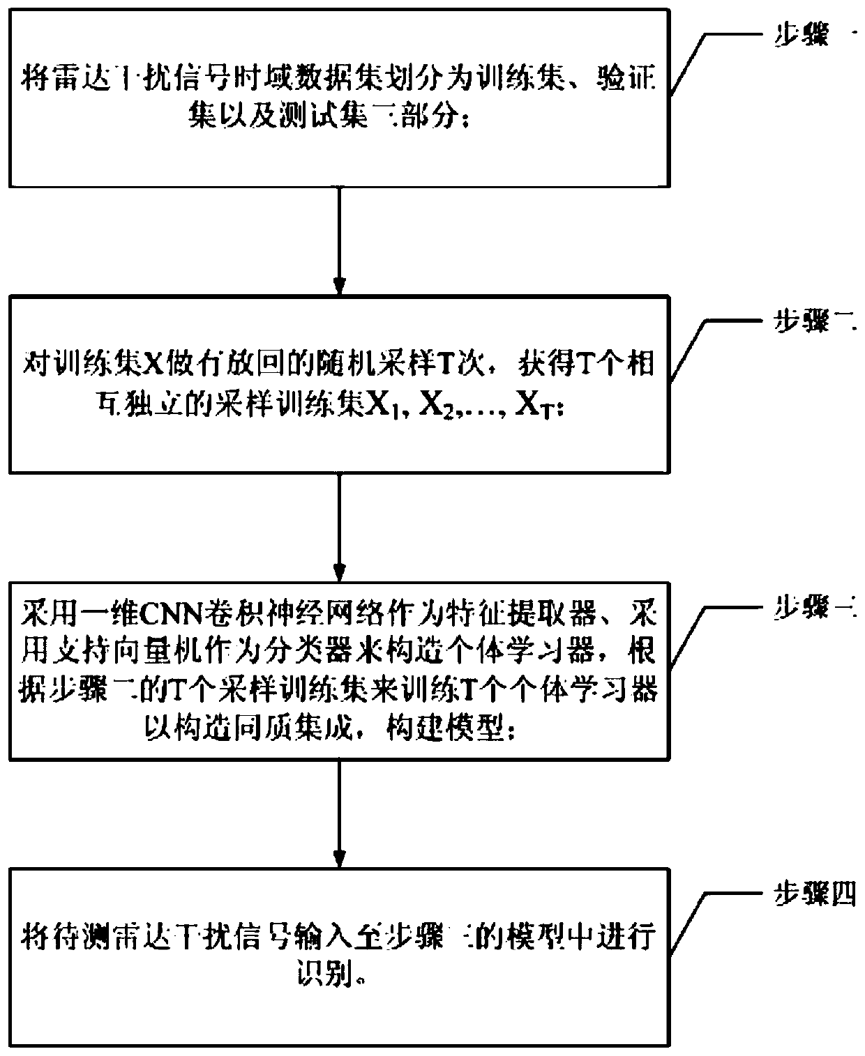
[0021] Specific implementation mode one: combine figure 1 To illustrate this embodiment, the radar interference signal recognition method based on deep convolutional neural network integration includes the following steps:

[0022] Step 1. Divide the radar jamming signal time domain data set into three parts: training set, verification set and test set;

[0023] The training set is denoted as X, and the number of training samples is denoted as m;

[0024] The process of dividing the radar interference signal time domain data set in step 1 is as follows:

[0025] Step 11. Mark the original radar data to form a radar interference signal time domain data set: store each sample in a vector, the first 50% of the vector is marked as the real part data of the sample, and the last 50% is marked as the imaginary part of the sample part data;

[0026] Step 12: Randomly divide the radar interference signal time-domain data set into three mutually disjoint sets, which are training set,...

specific Embodiment approach 2

[0037] Embodiment 2: This embodiment provides another solution: CNN is selected as the feature extractor of the radar interference time domain signal, and different classifiers are selected to construct heterogeneous integration. The radar interference signal recognition method based on deep convolutional neural network integration includes the following contents:

[0038] 1. The radar jamming signal time domain data set is divided into three parts: training set, verification set and test set.

[0039] The radar interference signal time-domain data sets used in the present invention include 12 types in total, and the data dimension of each sample is composed of real part data and imaginary part data. In terms of data storage, each sample is stored in a vector, the first 50% of the vector is the real part data of the sample, and the last 50% is the imaginary part data of the sample. For the marked original radar jamming signal time-domain data set, it needs to be randomly divi...


PUM


Abstract

The invention discloses a radar interference signal identification method based on deep CNN (Convolutional Neural Network) integration, belongs to the field of radar signal identification, and aims tosolve the problems of low identification accuracy and weak robustness of an identification system caused by overfitting and poor model generalization capability of an existing deep learning model foridentifying radar signals. The radar interference signal identification method comprises: a first step of dividing a radar interference signal time domain data set into a training set, a verificationset and a test set; a second step of performing replaced random sampling on the training set X for T times to obtain T mutually independent sampling training sets; a third step of adopting a one-dimensional CNN as a feature extractor and adopting a support vector machine as a classifier to construct individual learners, and training T individual learners according to the T sampling training setsin the second step to construct homogeneous integration and construct a model; and a fourth step of inputting a to-be-detected radar interference signal into the model in the third step for identification.

Description

technical field [0001] The invention belongs to the field of radar signal identification, and relates to a technology for identifying radar signals by using a convolutional neural network. Background technique [0002] With the continuous improvement of the level of science and technology, electronic warfare has become an important means of combat in modern warfare. In the increasingly complex electromagnetic environment of the battlefield, the anti-interference ability of radar has also become the key to the victory or defeat of the war. Ground identification and classification are the foundation and key of radar anti-jamming technology. The key step in the identification process of radar jamming signals is the extraction of characteristic parameters. However, with the rapid development of modern militarization technology, the forms of radar jamming signals are becoming more and more complex. If you continue to rely on manual experience to extract artificial features, it wi...

Claims


Application Information

Patent Timeline
IPC IPC(8): G01S7/36G01S7/02G06K9/62
CPCG01S7/36G01S7/021G06F18/2411G06F18/214
Inventor 张浩宇陈雨时于雷位寅生叶春茂李迎春
Owner HARBIN INST OF TECH
Learn More