Optical imaging system and display device
An optical imaging system and display device technology, applied in optics, optical components, installation, etc., can solve the problems of easy deformation of the lens barrel and reduced assembly strength, so as to avoid the easy deformation of the lens barrel, increase the wall thickness, and improve the assembly. The effect of standing strength
- Summary
- Abstract
- Description
- Claims
- Application Information
AI Technical Summary
Problems solved by technology
Method used
Image

Examples
Embodiment 1
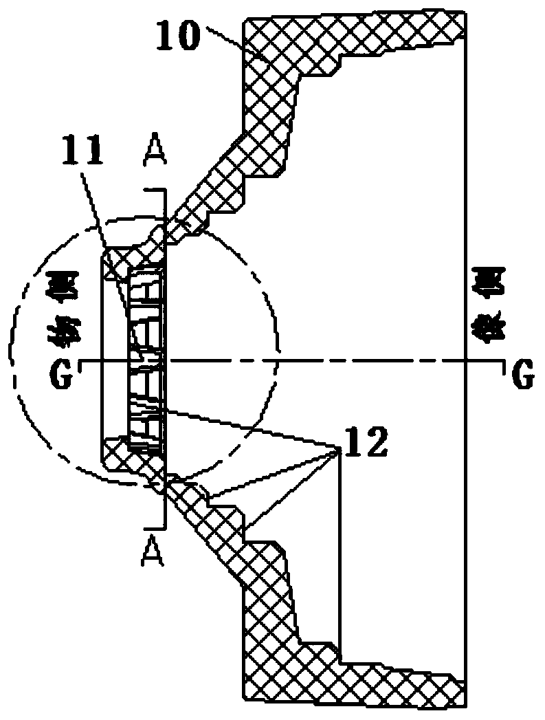
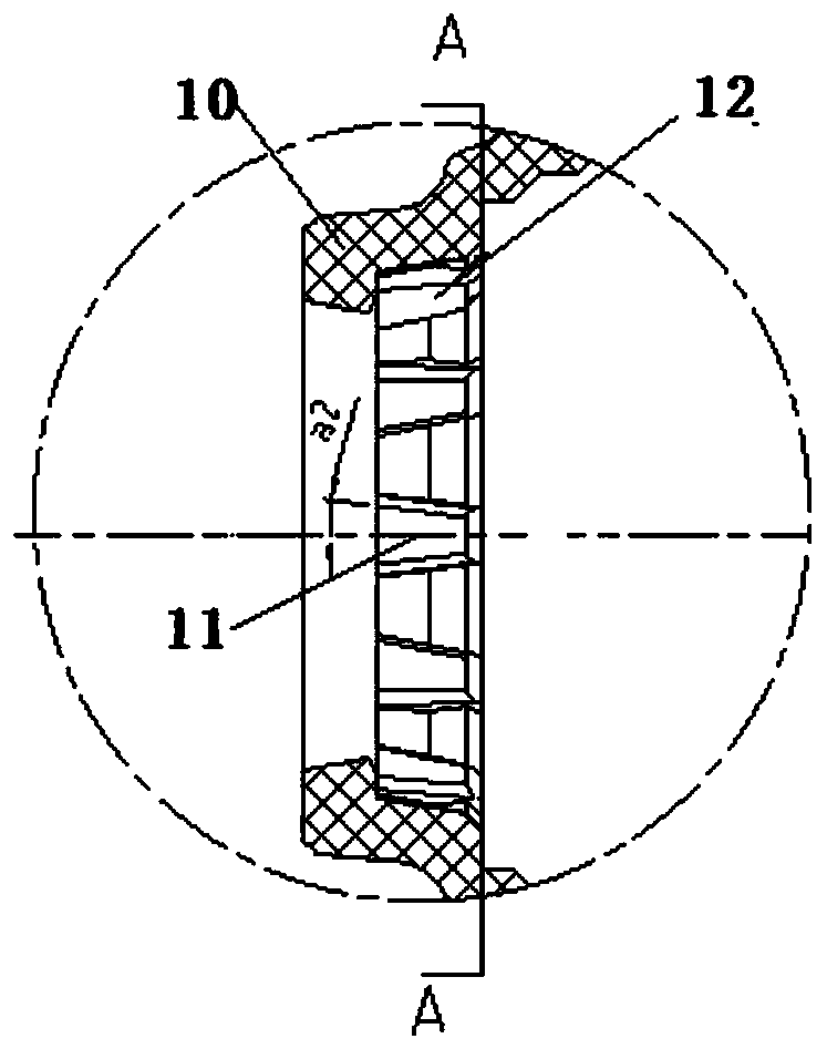
[0045] like Figure 1 to Figure 10 As shown, in Embodiment 1 of the present invention, the optical imaging system includes a plurality of bosses 11 and a plurality of grooves 21 corresponding to the plurality of bosses 11, and the plurality of bosses 11 are along the circumference of the lens barrel 10 The plurality of grooves 21 are arranged at intervals along the circumferential direction of the lens 20 .
[0046] According to the above setting, the one-to-one matching arrangement of a plurality of bosses 11 and a plurality of grooves 21 enables the lens 20 to be more embedded in the lens barrel 10, and the contact area between the lens 20 and the lens barrel 10 is larger, thereby better The assembly strength of the lens barrel 10 and the lens 20 has been greatly improved, and the problem that the lens barrel 10 is easily deformed when the lens barrel 10 and the lens 20 are assembled due to the small assembly strength is more effectively avoided, and the optical imaging syst...
Embodiment 2
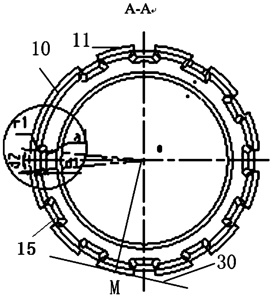
[0077] like Figure 12 to Figure 18As shown, in the second embodiment of the present invention, the optical imaging system includes a plurality of bosses 11 and a plurality of grooves 21 corresponding to the plurality of bosses 11, the difference between the second embodiment and the first embodiment It lies in the number of bosses 11 and grooves 21 . In the second embodiment, 21 bosses 11 are arranged at intervals along the circumference of the lens barrel 10 , and 21 grooves 21 are arranged at intervals along the circumference of the lens 20 .
[0078] like Figure 14 As shown, different from the first embodiment, in the second embodiment, the projection of the boss 11 on the first plane 30 is an isosceles triangle, and when the distance between the outer surface of the boss 11 and the axis of the lens barrel is the largest The point at point M is point M, and the tangent plane at point M is the first plane 30 . In the above arrangement, the boss 11 is arranged as an isos...
PUM
 Abstract
Description
Claims
Application Information
 - Generate Ideas
- Intellectual Property
- Life Sciences
- Materials
- Tech Scout
- Unparalleled Data Quality
- Higher Quality Content
- 60% Fewer Hallucinations
Browse by: Latest US Patents, China's latest patents, Technical Efficacy Thesaurus, Application Domain, Technology Topic, Popular Technical Reports.
© 2025 PatSnap. All rights reserved.Legal|Privacy policy|Modern Slavery Act Transparency Statement|Sitemap|About US| Contact US: help@patsnap.com