Supporting structure and display device

A supporting structure and flexible display technology, which is applied to identification devices, housings with display/control units, instruments, etc., can solve problems such as bending resistance, poor impact resistance, reduced reliability and stability, and achieve enhanced Effects of impact resistance, improved reliability and stability, enhanced ability to restore flatness

Active Publication Date: 2020-02-07
BOE TECH GRP CO LTD
View PDF18 Cites 64 Cited by
  • Summary
  • Abstract
  • Description
  • Claims
  • Application Information

AI Technical Summary

Problems solved by technology

[0003] However, as the flexible display panel becomes lighter and thinner, the overall bending resistance and impact resistance are poor; the reliability and stability of the product are reduced

Method used


Image

  • Supporting structure and display device
  • Supporting structure and display device
  • Supporting structure and display device

Examples


Embodiment 1

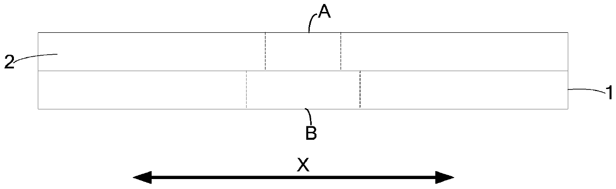
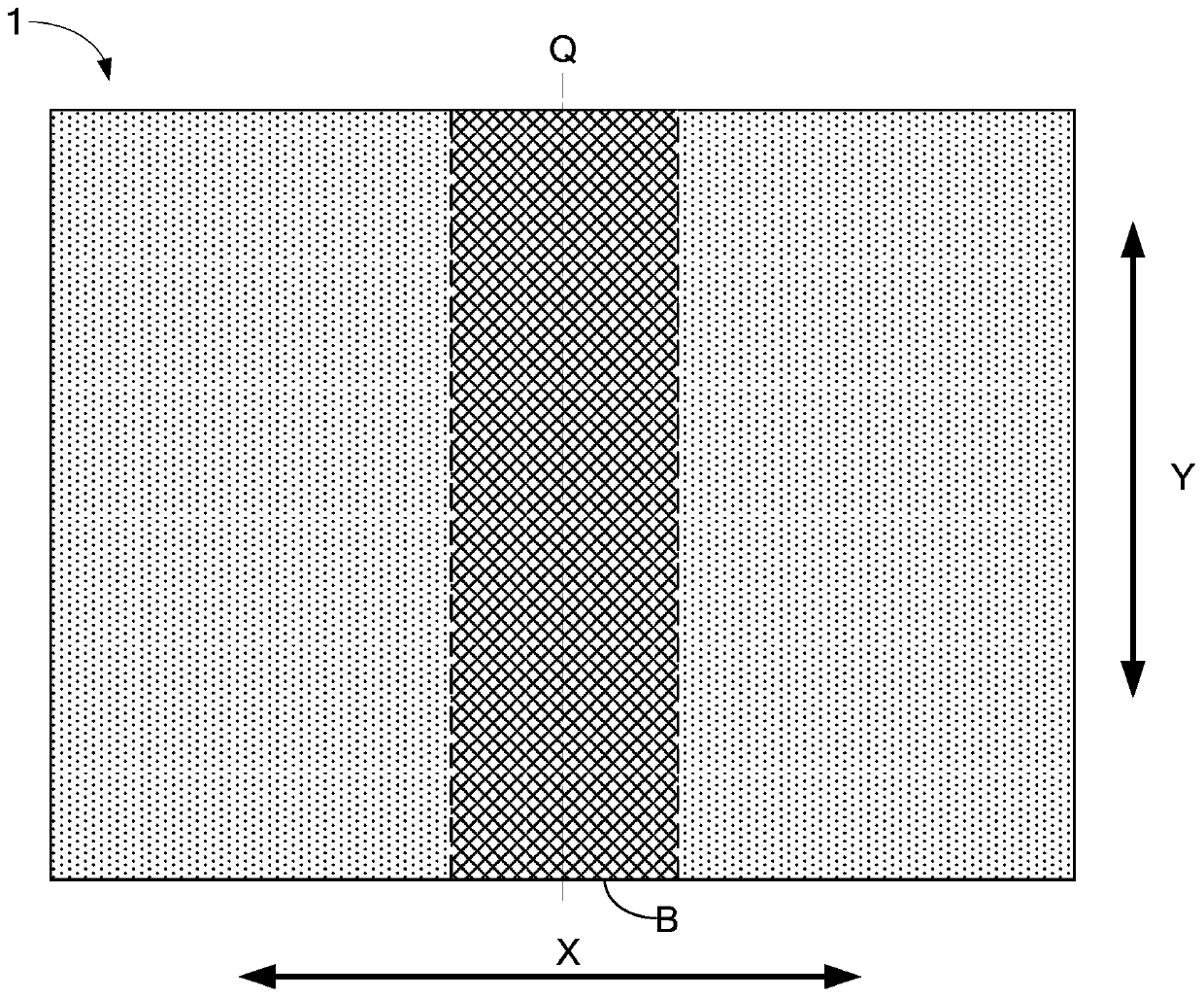
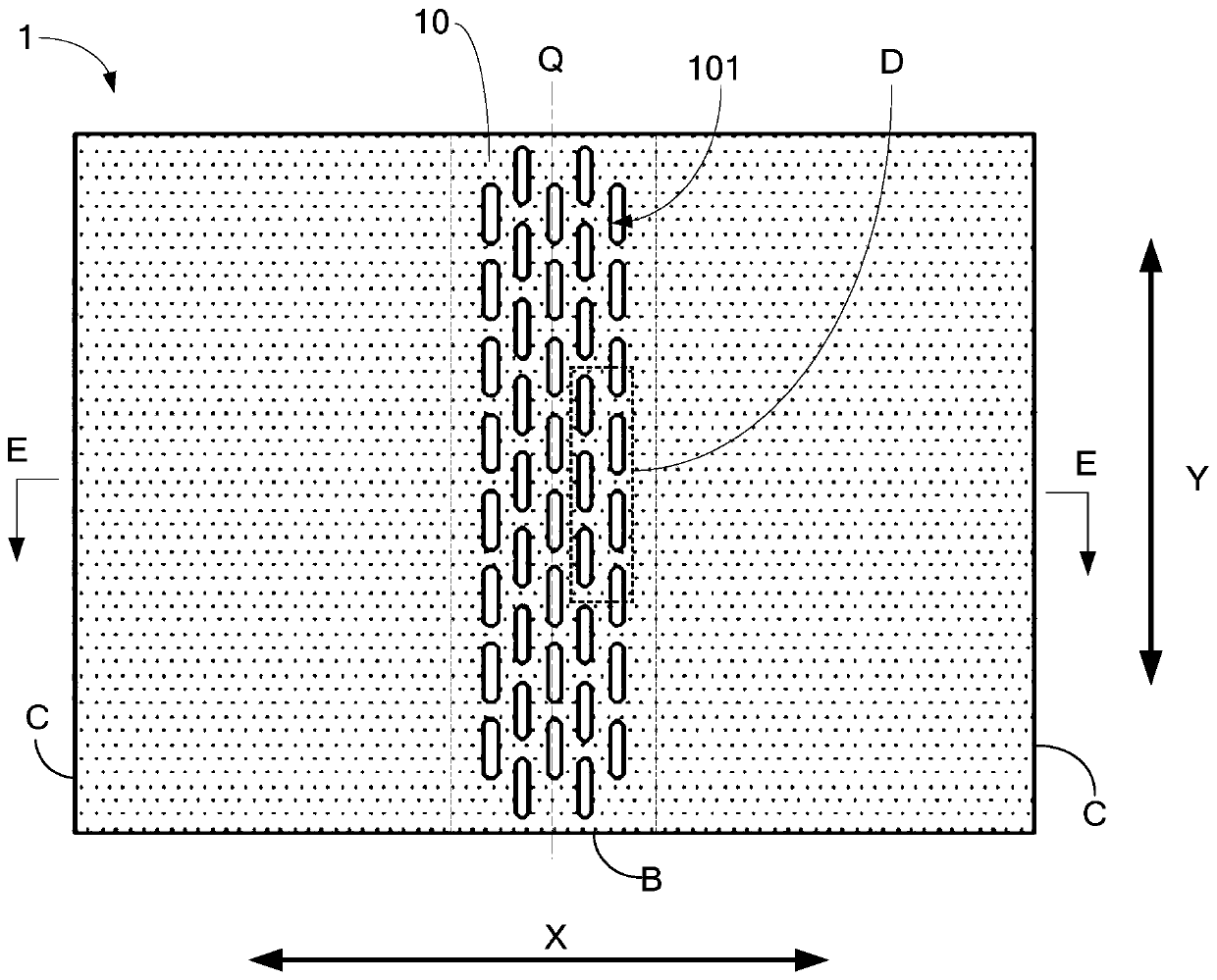
[0088] like image 3 As shown, the hollow area B of the support structure 1 may include the first portion 10 , and the plurality of hollow holes may include a plurality of first hollow holes 101 formed in the first portion 10 . The first portion 10 may cover the entire hollow area B, and the orthographic projection of the first portion 10 on the flexible display panel 2 completely covers the bendable area A.

[0089] Optionally, the first portion 10 may be arranged symmetrically with respect to the bending axis Q, so that the ability to disperse stress on both sides of the bending axis Q is relatively balanced, so as to avoid damage to the supporting structure. For example, the first portion 10 can be rectangular, but not limited thereto, and can also be irregular, depending on the actual situation.

[0090] In this embodiment, a plurality of first hollow holes 101 can be arranged in an array along the second direction X and the first direction Y, and the adjacent first hollo...

Embodiment 2

[0106] The main difference between the second embodiment and the first embodiment is that the first part 10 does not cover the entire hollow area B; other design concepts can be the same as those of the first embodiment, but are not limited thereto, and can also be different, depending on the specific circumstances .

[0107] Specifically, such as Figure 6 to Figure 8 As shown, the first part 10 can be located in the middle of the hollow area B, and the hollow area B can also include a second part 11, and the second part 11 is located on opposite sides of the first part 10 in the first direction Y, that is, : The second part 11 is located at the edge of the hollow area B.

[0108] For example, both the first portion 10 and the second portion 11 are arranged symmetrically with respect to the bending axis Q; so that the ability to disperse stress on both sides of the bending axis Q is relatively balanced, so as to avoid damage to the supporting structure 1 .

[0109]Specifica...

Embodiment 3

[0126] The main difference between the third embodiment and the second embodiment is: in order to avoid the situation that the edge area of ​​the hollowed-out area B is prone to breakage, when designing the hollowed-out area B in this embodiment, the total area of ​​the second hollowed-out hole 111 is compared with the total area of ​​the second part 11 The ratio between the total areas of the plurality of first hollow holes 101 is designed to be smaller than the ratio between the total area of ​​the first part 10, which can increase the rigidity of the second part 11, thereby increasing the resistance of the second part 11 The ability to destroy; and other design concepts and embodiment two can be the same, but not limited to this, also can be different, depending on the specific circumstances.

[0127] In the following, only the differences between this embodiment and the second embodiment will be described in detail.

[0128] In this embodiment, in order to make the ratio b...


PUM


Abstract

The application relates to a supporting structure and a display device. The supporting structure is arranged at one side of a flexible display panel, the flexible display panel comprises a bendable area, a bending axis corresponding to the bendable area extends on a first direction, wherein the supporting structure comprises a hollow-out area with a positive projection capable of completely covering the bendable area on the display panel, the hollow-out area comprises a first part formed with multiple first hollow-out holes, second parts located at two opposite sides of the first part on the first direction, wherein multiple second hollow-out holes are formed on the second parts; a specific value of the total area of multiple second hollow-out holes and the total area of the second parts is different from that of the total area of multiple first hollow-out holes and the first part, thereby guaranteeing the structure stability of the supporting structure and enhancing the shock resistance and bending resistance of the flexible display panel.

Description

technical field [0001] The present application relates to the field of display technology, in particular, to a support structure and a display device. Background technique [0002] With the development of display technology, flexible display panels such as foldable, stretchable and rollable are gradually entering the sight of consumers. In order to facilitate bending or recovery of the flexible display panel, it is necessary to make the flexible display panel thinner and lighter. [0003] However, as the flexible display panel becomes lighter and thinner, the overall bending resistance and impact resistance are poor; the reliability and stability of the product are reduced. [0004] It should be noted that the information disclosed in the above background technology section is only used to enhance the understanding of the background of the application, and therefore may include information that does not constitute prior art known to those of ordinary skill in the art. Con...

Claims


Application Information

Patent Timeline
Patent Type & Authority Applications(China)
IPC IPC(8): G09F9/30
CPCG09F9/301Y02E10/549H10K77/111H10K2102/311H05K5/0017
Inventor 曹方旭王浩然董栗明周永红蔡宝鸣曹学阳
Owner BOE TECH GRP CO LTD
Why Eureka
Try Eureka