Rectifying circuit by utilizing saturable mutual inductor

A rectifier circuit and bridge rectifier circuit technology, applied in the field of rectifiers, can solve the problems of fast switching speed and large output current, and achieve the effects of stable output waveform, large output current and fast switching control speed.

Pending Publication Date: 2020-02-07
CHAOYANG POWER SUPPLY COMPANY OF STATE GRID LIAONING ELECTRIC POWER SUPPLY +2
View PDF0 Cites 0 Cited by
  • Summary
  • Abstract
  • Description
  • Claims
  • Application Information

AI Technical Summary

Problems solved by technology

Therefore, the MOS-FET switching speed is fast and the output current is large

Method used


Image

  • Rectifying circuit by utilizing saturable mutual inductor
  • Rectifying circuit by utilizing saturable mutual inductor

Examples


Embodiment Construction

[0020] The specific embodiments provided by the present invention will be described in detail below in conjunction with the accompanying drawings.

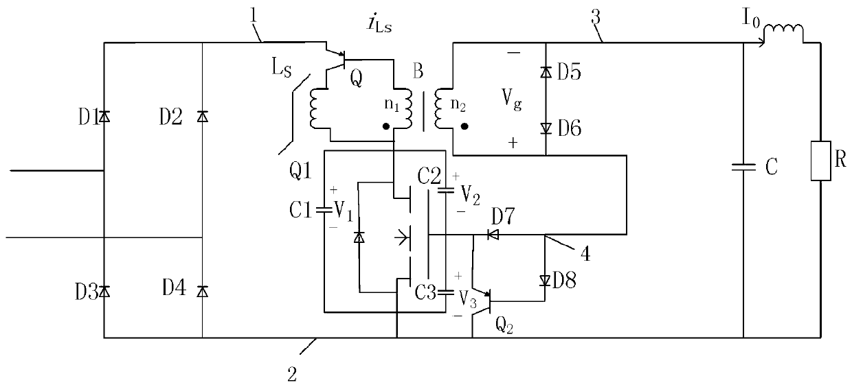
[0021] Such as figure 1 As shown, a rectifier circuit using a saturable transformer includes a bridge rectifier circuit, a saturable transformer circuit and an LC filter circuit sequentially connected from the input terminal to the output terminal;

[0022] The components of the saturable transformer circuit include a first triode Q, a first inductance L S , Transformer B, MOS-FET tube Q1, second triode Q2, also includes first capacitor C1, second capacitor C2, third capacitor C3, fifth diode D5, sixth diode D6, seventh Diode D7, eighth diode D8; their circuit connections are as follows:

[0023] 1) The upper end (1) of the output end of the bridge rectifier circuit is sequentially connected in series with the first triode Q and the first inductor L S and the MOS-FET tube Q1, the lower end of the MOS-FET tube Q1 is connected to...


PUM


Abstract

A rectifying circuit by utilizing a saturable mutual inductor comprises a bridge type rectifying circuit, a saturable mutual inductor circuit and an LC filter circuit which are sequentially connectedfrom an input end to an output end. The saturable mutual inductor circuit comprises a first triode Q, a first inductor LS, a transformer B, an MOS-FET tube Q1, a second triode Q2, a first capacitor C1, a second capacitor C2, a third capacitor C3, a fifth diode D5, a sixth diode D6, a seventh diode D7 and an eighth diode D8. By improving a rectifying circuit commonly used in the UPS and due to theconstraint relation of the MOS-FET, the output condition of the current transformer can be effectively controlled, so that the switching control speed is high, the output current is large, the systemreaction sensitivity is higher, and the output waveform is more stable. The circuit can be used as a rectifier of a two-port device, can be applied to a plurality of rectifying circuits, provides convenience for a rectifying device in the UPS, and has positive guiding significance in engineering practice.

Description

technical field [0001] The invention relates to the technical field of rectifiers, in particular to a rectifier circuit using a saturable transformer. Background technique [0002] With the development of UPS technology, people have higher and higher requirements for the performance and stability of the rectifier circuit. Therefore, it is urgent to seek a new type of rectification circuit and rectification equipment with high rectification efficiency and stable output waveform. The MOS-FET switch in the SRS circuit has high sensitivity, and the output current of the FET is controlled by the induced current in the transformer. Therefore, the MOS-FET switching speed is fast and the output current is large. [0003] The current of a saturated current transformer is output proportional to time. Therefore, this will act as a constraint on the MOS-FET. When the transformer does not reach saturation, the rectified voltage is approximately equal to the sum of the voltages of all...

Claims


Application Information

Patent Timeline
Patent Type & Authority Applications(China)
IPC IPC(8): H02M7/217H02M3/335
CPCH02M3/33592H02M7/217
Inventor 杜荣宇李大伟王宏图卢卓群张福玲毛鑫张艳华李和平宋家琪刘英张卫军曲衷正李龙妹刘恬恬
Owner CHAOYANG POWER SUPPLY COMPANY OF STATE GRID LIAONING ELECTRIC POWER SUPPLY
Why Eureka
Try Eureka