
Pulse trigger self-locking button switch based on T'trigger

A pulse trigger and flip-flop technology, applied in the field of digital circuits, can solve the problems of large space occupation and difficulty in integration, and achieve the effects of reduced space, low cost of integrated circuits, and simple switch structure

Pending Publication Date: 2020-02-07
杭州率通电子科技有限公司
View PDF0 Cites 0 Cited by
  • Summary
  • Abstract
  • Description
  • Claims
  • Application Information

AI Technical Summary

Problems solved by technology

[0003] Aiming at the deficiencies of the prior art, the present invention provides a pulse-triggered self-locking button switch based on a T' trigger, which realizes the conduction and Turn off to realize the self-locking turn-on and turn-off of the switch, so that the circuit can overcome the problems of large space occupation and difficult integration, and the application scenarios are more extensive

Method used


Image

  • Pulse trigger self-locking button switch based on T'trigger
  • Pulse trigger self-locking button switch based on T'trigger
  • Pulse trigger self-locking button switch based on T'trigger

Examples


Embodiment Construction

[0021] Reference will now be made in detail to the exemplary embodiments, examples of which are illustrated in the accompanying drawings. In the following descriptions and drawings, unless otherwise indicated, the same numerals in different drawings indicate the same or similar elements. The implementations described in the following exemplary embodiments do not represent all implementations consistent with this application. Rather, they are merely examples of arrangements consistent with aspects of the application as recited in the appended claims. Each embodiment in this specification is described in a progressive manner.

[0022] It should be noted that all directional indications (such as up, down, left, right, front, back...) in the embodiments of the present application are only used to explain the relationship between the components in a certain posture (as shown in the drawings). Relative positional relationship, movement conditions, etc., if the specific posture cha...


PUM


Abstract

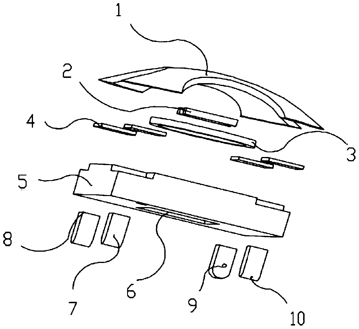
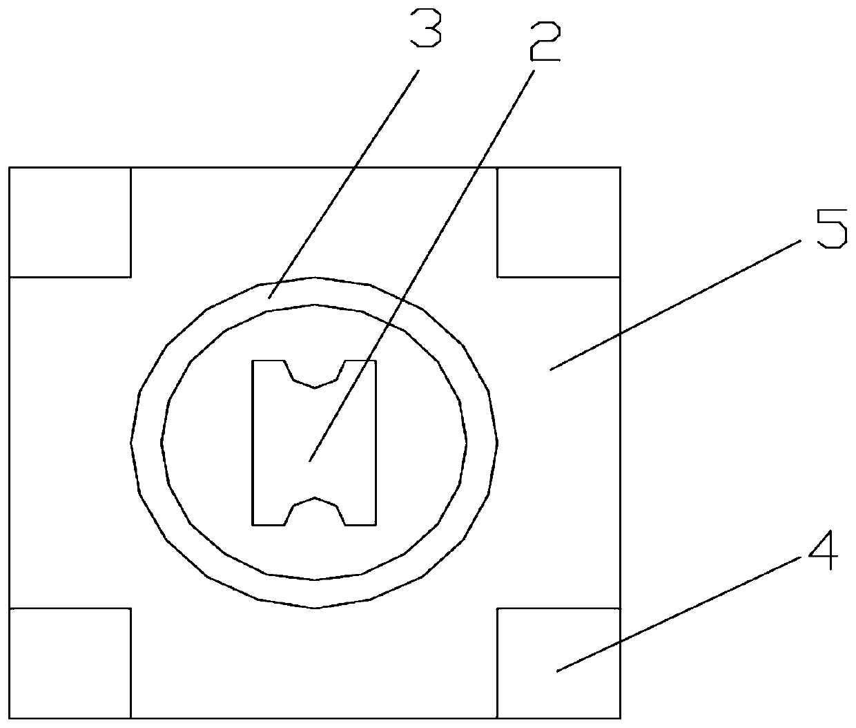
The invention discloses a pulse trigger self-locking button based on a T'trigger, and belongs to the field of circuit type switches. Short-circuit metal sheets are attached to four corners of a buttonbase and connected with a voltage input Vin + end; the short-circuit metal ring is attached to the upper surface of the button base; the lower surface of the button base is provided with a first pin,a second pin, a third pin and a fourth pin which are respectively connected with a voltage input Vin + end, a voltage input GND end, a voltage output Vout + end and a voltage output GND end of the embedded logic control circuit; four corners of the contact metal hollowed-out raised button are clung to the four-corner short-circuit metal sheet on the button base; and a pulse trigger switch S1 is formed between the contact metal hollow bulge button and the short-circuit metal ring. According to the invention, the MOS tube is controlled to be turned off to realize self-locking and self-opening of the switch by adopting a T'trigger turnover principle, so that the control of a microprocessor is omitted, the cost of the whole system is saved, and the application scene of the contact button switch is wider.

Description

technical field [0001] The invention relates to the technical field of digital circuits, in particular to a pulse-triggered self-locking button switch based on a T' trigger. Background technique [0002] The known self-locking switches are all mechanical self-locking. This design has some disadvantages: it takes up a lot of space, it is not conducive to high integration, the mechanical contact is not sensitive, and the mechanical part is easy to be damaged after a long time. There will be a shaking process in the process, and it is necessary to manually set the debounce circuit or debounce program, etc., and the currently commonly used button self-locking circuit uses a processor to control the triode or MOS tube to realize the self-locking of the circuit, so it is necessary to add in the circuit Microprocessor, this will not only take up the resources of the microprocessor, but also increase the cost and complexity of the entire circuit in some places where the microprocess...

Claims


Application Information

Patent Timeline
Patent Type & Authority Applications(China)
IPC IPC(8): H03K17/965
CPCH03K17/965
Inventor 李福生张伟业徐磊
Owner 杭州率通电子科技有限公司
Learn More