Floor brush and assembling method thereof

A technology for assembling columns and assembling parts, which is applied in the direction of the suction nozzle, etc., can solve the problems such as the weak connection between the side plate and the floor brush shell, and the cumbersome way to pick and place the roller brush, so as to achieve simple and convenient pick and place, simple and convenient operation steps, The effect of reducing the overall volume

Pending Publication Date: 2020-02-11
XIAOGOU ELECTRIC INTERNET TECH BEIJING CO LTD
View PDF0 Cites 2 Cited by
  • Summary
  • Abstract
  • Description
  • Claims
  • Application Information

AI Technical Summary

Problems solved by technology

[0004] In view of the above analysis, the embodiment of the present invention aims to provide a ground brush and its assembly method to solve the problems in the prior art that the connection between the side plate of the ground brush and the ground brush housing is not firm, and the method of picking and placing the roller brush is cumbersome.

Method used


Image

  • Floor brush and assembling method thereof
  • Floor brush and assembling method thereof
  • Floor brush and assembling method thereof

Examples


Embodiment 1

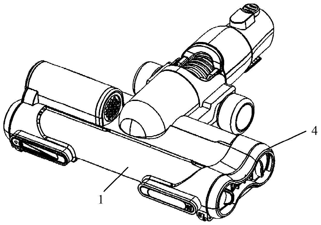
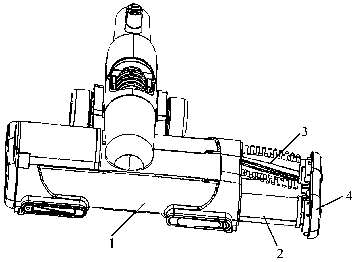
[0059] This embodiment provides a ground brush, see Figure 1-Figure 11 As shown, it includes a main housing 1, a rolling brush assembly (for example, a front rolling brush assembly 2 or / and a rear rolling brush assembly 3), a side cover assembly 4, and a rolling brush transmission assembly for driving the rolling brush assembly to rotate. Components and the roller brush transmission assembly are located in the main housing 1, one end of the roller brush assembly is connected to the roller brush transmission assembly, the other end of the roller brush assembly is detachably connected to the side cover assembly 4, and the roller brush assembly is relatively to the side cover assembly 4 Can be rotated, and the side cover assembly 4 is buckled on one end of the main casing 1 .

[0060]Compared with the prior art, in the floor brush provided by this embodiment, the side cover assembly 4 is detachably connected to the main housing 1 by buckling. When the floor brush collides with w...

Embodiment 2

[0093] This embodiment provides a ground brush assembly method for the ground brush provided in Embodiment 1, including the following steps:

[0094] Step 1: Assemble one end of the roller brush assembly to the inner side of the side cover assembly 4;

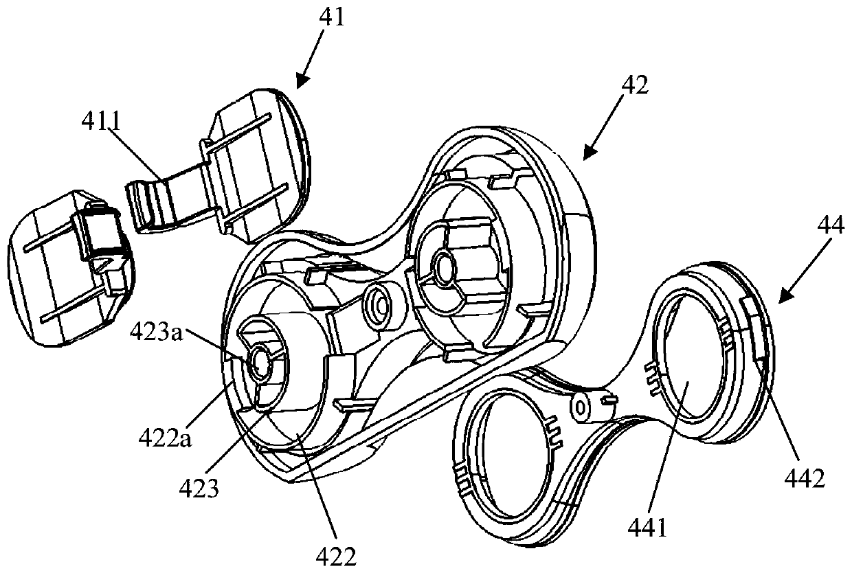
[0095] Specifically, the first step is to bring the roller brush assembly close to the second assembly part 422, rotate the roller brush end cover 5 so that the notch 51 corresponds to the convex plate 422a, and place the roller brush end cover 5 in the second assembly part 422 at the same time , the rotating shaft of the roller brush is inserted into the assembly hole 423a, and then the roller brush end cover 5 is rotated clockwise or counterclockwise, so that the notch 51 is misaligned with the convex plate 422a, and one end of the roller brush assembly is assembled to the inner side of the side cover assembly;

[0096] Step 2: Insert the other end of the roller brush assembly into the main housing 1;

[0097] Step 3: Move t...


PUM


Abstract

The invention relates to a floor brush and an assembling method thereof, and relates to the technical field of a cleaning device. The problems that in the prior art, the connection of a side plate ofthe floor brush and a casing of the floor brush is infirm, and the taking and putting mode of a rolling brush is complicated are solved. The floor brush provided by the invention comprises a main casing, a rolling brush assembly, a side cover assembly and a rolling brush transmission assembly, wherein the rolling brush transmission assembly is used for driving the rolling brush assembly to rotate;the rolling brush assembly and the rolling brush transmission assembly are positioned in the main casing; one end of the rolling brush assembly is connected with the rolling brush transmission assembly; the other end of the rolling brush assembly is detachably connected with the side cover assembly; the rolling brush assembly can rotate relative to the side cover assembly; and the side cover assembly is clamped and buckled at one end of the main casing. The floor brush has the advantages that the side cover assembly is detachably connected with the main casing in a clamped and buckled mode; looseness cannot easily occur between the side cover assembly and the main casing; the connection between the side cover assembly and the main casing is firm; the rolling brush assembly and the side cover assembly are detachably connected; and when the side cover assembly is taken down, the rolling brush assembly can be taken out from the main casing together, so that the rolling brush can be simply, conveniently and fast taken and put.

Description

technical field [0001] The invention relates to the technical field of cleaning devices, in particular to a floor brush and an assembly method thereof. Background technique [0002] In the existing floor brushes, most of the side panels are connected to the floor brush shell by magnetic attraction. Although this assembly method is simple and convenient, when the floor brush collides with the wall, table cabinet, etc., the side plate and the floor brush shell will be damaged. The body is prone to loosening, resulting in an insecure connection between the two. [0003] In addition, since there is no connecting structure between the side plate and the roller brush, when taking and placing the roller brush, it is necessary to remove the side plate from the floor brush housing first, and then take out or put in the roller brushes one by one. The method is relatively cumbersome and inconvenient to operate. Contents of the invention [0004] In view of the above analysis, the e...

Claims


Application Information

Patent Timeline
Patent Type & Authority Applications(China)
IPC IPC(8): A47L9/04
CPCA47L9/04
Inventor 檀冲宋武斌程世及王东林润
Owner XIAOGOU ELECTRIC INTERNET TECH BEIJING CO LTD
Why Eureka
Try Eureka