Electromagnetic suspension track train

A technology for maglev tracks and trains, applied in motor vehicles, electric vehicles, railway vehicles, etc., can solve the problems of high derailment risk of suspension racks and large minimum turning radius of maglev track trains, so as to improve work safety and reliability, improve The effect of rotation flexibility and large rotation range

Inactive Publication Date: 2020-02-11
CHINA RAILWAY CONSTR HEAVY IND
View PDF8 Cites 0 Cited by
  • Summary
  • Abstract
  • Description
  • Claims
  • Application Information

AI Technical Summary

Problems solved by technology

[0002] In the existing maglev rail train, the rotation of the suspension frame is completely dependent on the guide wheels set on the suspension beam. During the travel, the maglev track forces the suspension frame with the guide wheels to rotate. The suspension frame under this structure has a high risk of derailment
Moreover, the units that make up the suspension frame are in a non-movable frame structure. When the maglev rail train travels to the curved maglev track, the relative rotation between the suspension frame units is required to realize the rotation of the maglev rail train. For this, each Due to structural limitations, the rotation angle between suspension frame units has a limit value, resulting in a large minimum turning radius of the maglev rail train, so that the maglev rail train must pass through the maglev track with a large radius to achieve direction reversal

Method used


Image

  • Electromagnetic suspension track train
  • Electromagnetic suspension track train
  • Electromagnetic suspension track train

Examples


Embodiment Construction

[0041] In order to understand the above-mentioned purpose, features and advantages of the present invention more clearly, the present invention will be further described in detail below in conjunction with the accompanying drawings and specific embodiments. It should be noted that, in the case of no conflict, the embodiments of the present invention and the features in the embodiments can be combined with each other.

[0042] In the following description, many specific details are set forth in order to fully understand the present invention. However, the present invention can also be implemented in other ways different from those described here. Therefore, the protection scope of the present invention is not limited by the specific details disclosed below. EXAMPLE LIMITATIONS.

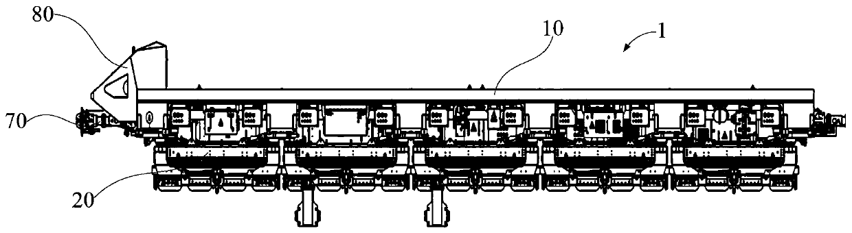
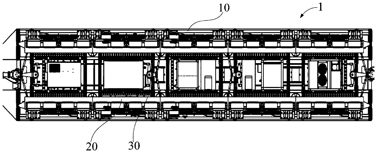
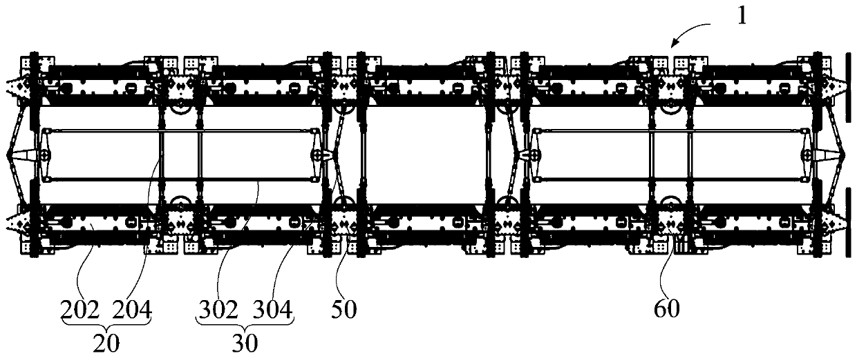
[0043] Refer below Figure 1 to Figure 7 A maglev rail train 1 according to some embodiments of the present invention is described.

[0044] In view of this, according to the embodiment of the presen...


PUM


Abstract

The inventio provides an electromagnetic suspension track train. The electromagnetic suspension track train comprises a train frame, a suspension frame connected with the train frame, a guiding wheeland a guiding mechanism, wherein the suspension frame comprises a plurality of suspension units sequentially connected in a rotatable mode, each suspension unit is of a closed four-linkage structure,the guiding wheel is arranged on one of the suspension units, the guiding wheel makes contact with an electromagnetic suspension track, the guiding mechanism comprises a first rod group and second rodgroups, the first rod group is of a closed four-linkage structure, a plurality of the second rod groups are arranged, one end of each second rod group is connected with the first rod group, the otherend of each second rod group is rotatably connected with each suspension unit, the bent electromagnetic suspension track compels the suspension unit provided with the guiding wheel to twist, the twisted suspension units drives the first rod group to twist through the second rod groups, and the twisted first rod group drives the other suspension units to synchronously twist through the second rodgroups. The electromagnetic suspension track train realizes the technical effects of optimizing the structure of the suspension frame, improving rotation flexibility of the suspension frame, and improving work safety and reliability of the suspension frame.

Description

technical field [0001] The invention relates to the technical field of maglev trains, in particular to a maglev rail train. Background technique [0002] In the existing maglev rail train, the rotation of the suspension frame depends entirely on the guide wheels provided on the suspension beams. During the running process, the maglev track forces the suspension frame with the guide wheels to rotate. The suspension frame under this structure has a high risk of derailment. Moreover, the units that make up the suspension frame are in a non-movable frame structure. When the maglev rail train travels to the curved maglev track, the relative rotation between the suspension frame units is required to realize the rotation of the maglev rail train. For this, each Due to structural limitations, the rotation angle between the suspension frame units has a limit value, resulting in a large minimum turning radius of the maglev rail train, so that the maglev rail train must pass through th...

Claims


Application Information

Patent Timeline
Patent Type & Authority Applications(China)
IPC IPC(8): B61B13/08B60L13/04B61F1/08
CPCB60L13/04B61B13/08B61F1/08
Inventor 刘飞香罗建利陈兵生刘斌朱震寰周小科邓志斌罗晓侃左后林
Owner CHINA RAILWAY CONSTR HEAVY IND
Why Eureka
Try Eureka