Supercharge Your Innovation With Domain-Expert AI Agents!

Method for obtaining high-precision detector orientation test result

A test result and detector technology, which is applied in the field of smoke detectors, can solve the problems of large numerical error, large smoke intake performance error, and the influence of smoke rising rate is not considered, and achieves the effect of low control precision requirements and high precision

Active Publication Date: 2020-02-11
深圳市高新投三江电子股份有限公司
View PDF13 Cites 0 Cited by
  • Summary
  • Abstract
  • Description
  • Claims
  • Application Information

AI Technical Summary

Problems solved by technology

[0003] Disadvantage 1: Since the response value of the detector to the test smoke concentration increases discretely and is limited by the detector’s response accuracy to the test smoke concentration, the value / single point value of a single position (response threshold) is used to represent a certain value. The numerical error of the moment (the moment when the detector reaches the response threshold) is large
[0004] The second disadvantage is that the method does not consider the influence of the smoke rate on the detector orientation
[0005] Disadvantage 3: The method does not consider the impact of the smoke start time on the detector orientation
[0006] Disadvantage 4: The method uses time to compensate for the error of the smoke-raising rate and the start time of the smoke-raising. By extending or shortening the smoke-raising time to ensure the smoke concentration of the smoke box test when the detector reaches the response threshold, and the test inside the detector within the compensation time The change of smoke concentration is complex, taking the detector response threshold in this state means that the error of smoke inlet performance in this direction is relatively large

Method used


Image

  • Method for obtaining high-precision detector orientation test result
  • Method for obtaining high-precision detector orientation test result
  • Method for obtaining high-precision detector orientation test result

Examples


Embodiment Construction

[0033] In order to make the purpose, technical solutions and advantages of the embodiments of the present invention clearer, a clear and complete description will be made below in conjunction with the technical solutions in the embodiments of the present invention. Obviously, the described embodiments are part of the embodiments of the present invention, and Not all examples. Based on the embodiments of the present invention, all other embodiments obtained by persons of ordinary skill in the art without making creative efforts belong to the protection scope of the present invention.

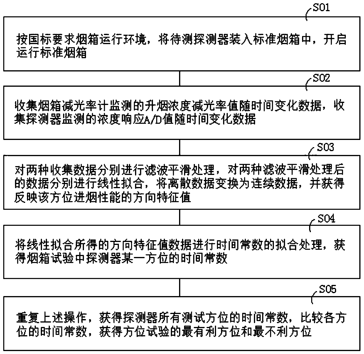
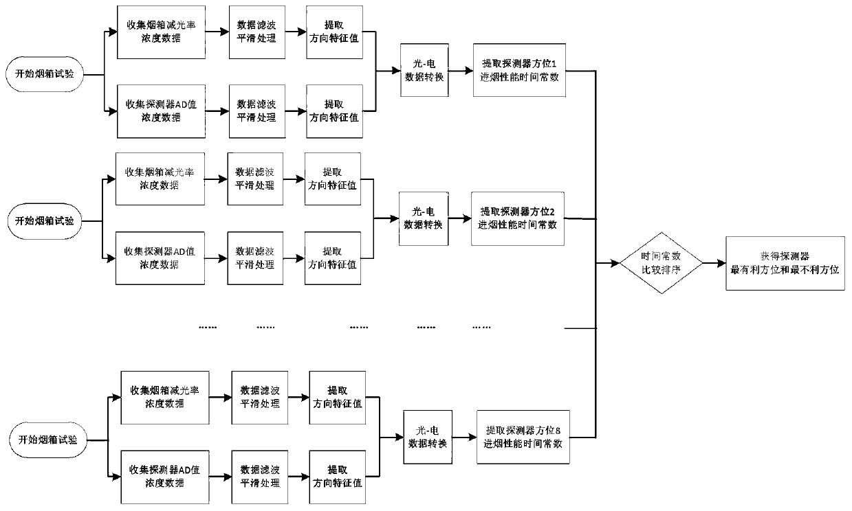
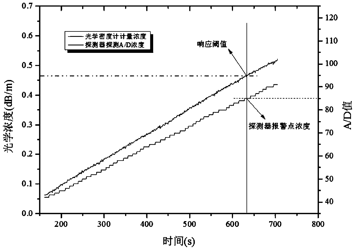
[0034] The method for obtaining high-precision detector azimuth test results in a preferred embodiment of the present invention, such as figure 1 shown, see also Figure 2-7 , which is implemented as follows:

[0035] SO1: According to the national standard requirements for the operating environment of the smoke box, put the detector to be tested into the standard smoke box, and open the standa...


PUM


Abstract

The invention relates to a method for obtaining a high-precision detector orientation test result. The method comprises the following steps: collecting time-varying data of a smoke rising concentration dimming rate value monitored by a smoke box dimming rate meter, and collecting time-varying data of a concentration response A / D value monitored by a detector; carrying out filtering smoothing on the two types of data, carrying out linear fitting on the two types of data after filtering smoothing, converting discrete data into continuous data, and obtaining an orientation feature value that canreflect the smoke input performance of the orientation; carrying out time constant fitting on the orientation feature value obtained by linear fitting to obtain a time constant of certain orientationof a detector during smoke box test; and repeating the above operations, obtaining time constants of all test orientations of the detector, comparing the time constants, and obtaining the most favorable orientation and the most unfavorable orientation of the orientation test. Thus, the requirements for the control precision of the smoke box in the aspects of smoke rising rate and smoke rising start time are lower, and an orientation test result of higher precision can be obtained.

Description

technical field [0001] The invention relates to the technical field of smoke detectors, in particular to a method for obtaining high-precision detector azimuth test results. Background technique [0002] The existing azimuth test method mainly refers to the azimuth test described in Section 4.3 of the GB4715-2005 specification for point-type smoke detectors. Smoke intake performance in different directions. The main method is to install the photoelectric detector in a standard smoke box, rotate the detector in increments of 45° and evenly divide it into 8 test positions, run the standard smoke box, and ensure that the airflow around the detector is (0.2±0.04)m / s, the test smoke is injected into the smoke box, and the test smoke concentration increases at a given linear growth rate Δm / Δt (the growth rate range is 0.015dB / m / min~0.1dB / m / min), usually taken as 0.05 dB / m / min, record and compare the response thresholds of these 8 azimuths of the detector, so as to obtain the mo...

Claims


Application Information

Patent Timeline
IPC IPC(8): G01N33/00G01N15/06
CPCG01N33/007G01N15/06G01N33/0072
Inventor 黄小青肖学波
Owner 深圳市高新投三江电子股份有限公司
Features
  • R&D
  • Intellectual Property
  • Life Sciences
  • Materials
  • Tech Scout
  • Unparalleled Data Quality
  • Higher Quality Content
  • 60% Fewer Hallucinations
Learn More