
Optical structure and manufacturing method thereof, light source system, and detection device

An optical structure, grating technology, applied in the field of optical detection, can solve problems such as large volume

Active Publication Date: 2020-02-11
BOE TECH GRP CO LTD
View PDF9 Cites 2 Cited by
  • Summary
  • Abstract
  • Description
  • Claims
  • Application Information

AI Technical Summary

Problems solved by technology

However, existing spectrometer equipment is usually too bulky and can only be used in laboratories

Method used


Image

  • Optical structure and manufacturing method thereof, light source system, and detection device
  • Optical structure and manufacturing method thereof, light source system, and detection device
  • Optical structure and manufacturing method thereof, light source system, and detection device

Examples


Embodiment Construction

[0033] The following will clearly and completely describe the technical solutions in the embodiments of the present disclosure with reference to the accompanying drawings in the embodiments of the present disclosure. Apparently, the described embodiments are only some of the embodiments of the present disclosure, not all of them. Based on the embodiments in the present disclosure, all other embodiments obtained by persons of ordinary skill in the art without making creative efforts belong to the protection scope of the present disclosure.

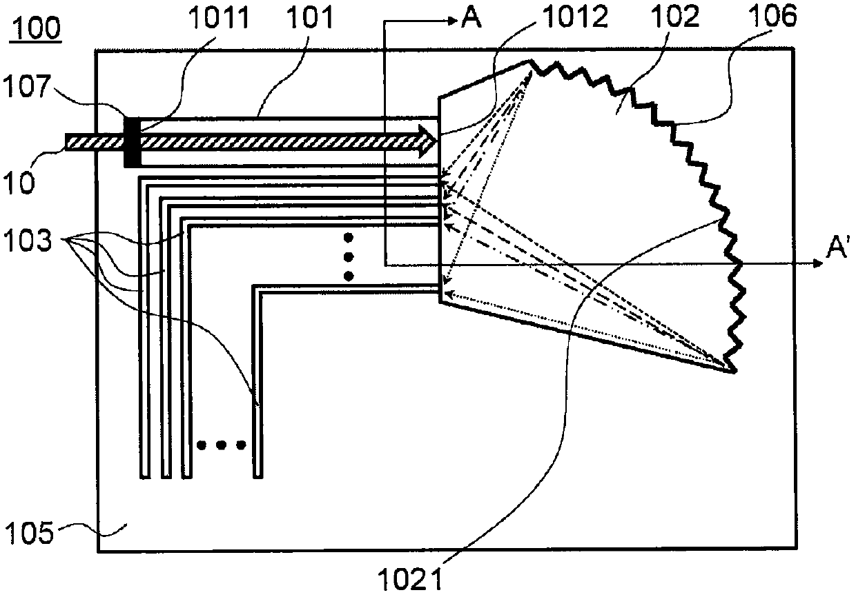
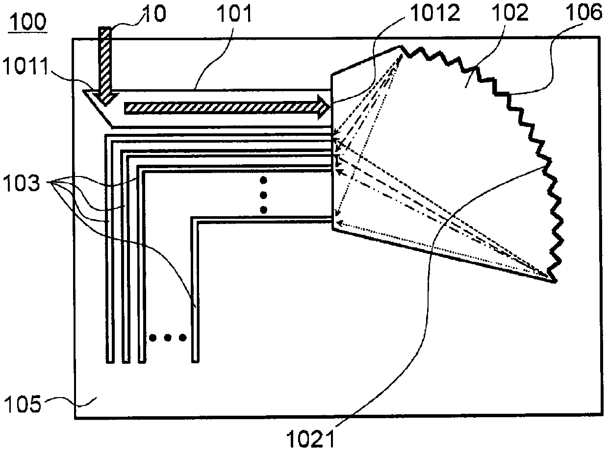
[0034] According to one aspect of the present disclosure, an optical structure is provided. Such as figure 1 with figure 2 As shown, the optical structure 100 includes: for guiding light (such as figure 1 Indicated by the arrow 10 in the optical waveguide 101), the optical waveguide includes a light incident surface 1011 and a light exit surface 1012; configured to split the light from the optical waveguide 101 into a plurality of monoc...


PUM


Abstract

The present disclosure provides an optical structure and a manufacturing method thereof, a light source system, and a detection device. A basic structure of a spectrum test and the manufacturing method thereof are simplified. The optical structure comprises an optical waveguide for transmitting light, wherein the optical waveguide comprises a light inlet surface and a light outlet surface; a colorseparation device disposed at the light outlet surface of the optical waveguide and configured to separate the light from the optical waveguide into multiple monochromatic light beams; and multiple monochromatic light output channels arranged at the light outlet surface of the color separation device, wherein multiple monochromatic light output channels are configured to output multiple monochromatic light beams from the color separation device.

Description

technical field [0001] The present disclosure relates to the technical field of optical detection, and in particular to an optical structure, a manufacturing method thereof, a light source system, and a detection device. Background technique [0002] Material calibration or quantitative analysis can be realized by utilizing the reflection, transmission, or absorption of specific wavelength light by microfluidics. However, existing spectrometer equipment is usually too bulky and can only be used in laboratories. Therefore, it is desired to provide a miniaturized spectrometer, increase the spectral range of the spectrometer, reduce the cost of the spectrometer, and thus increase the range of use of the spectrometer. Contents of the invention [0003] The disclosure provides an optical structure and a manufacturing method thereof, a light source system, and a detection device, which simplifies the basic structure of spectrum testing and the manufacturing method thereof. [...

Claims


Application Information

Patent Timeline
IPC IPC(8): G02B6/12G02B6/125G02B6/13G01N21/25
CPCG02B6/12004G02B6/125G02B6/13G01N21/25G02B6/12007G02B2006/12164G02B2006/12107G02B6/124G02B6/29304G02B6/136G02B6/132G01J3/0218G01J3/0205G01J3/021G01J3/0259G01J3/18G01J3/1838G01J3/1895G01J2003/2826G01J3/36B01L3/502715G01J3/0294G01J2003/1286G02B6/107
Inventor 孟宪芹王维谭纪风孟宪东陈小川高健王方舟梁蓬霞
Owner BOE TECH GRP CO LTD
Learn More