A battery shock absorber for new energy vehicles

A new energy vehicle and shock absorbing device technology, which is applied to secondary batteries, battery pack components, circuits, etc., can solve the problems of difficulty in battery disassembly and replacement, inconvenient installation of batteries, and general shock absorption effect, so as to achieve shock absorption Effect, ease of replacement, effect of enhancing architectural effect

Active Publication Date: 2020-11-17
梅梅
View PDF5 Cites 0 Cited by
  • Summary
  • Abstract
  • Description
  • Claims
  • Application Information

AI Technical Summary

Problems solved by technology

[0004] The purpose of the present invention is to overcome the disadvantages of the prior art that the device structure is simple, the shock absorption effect is general, it is inconvenient to install the battery, and it is difficult to disassemble and replace the battery, and to provide a battery shock absorber for new energy vehicles

Method used


Image

  • A battery shock absorber for new energy vehicles
  • A battery shock absorber for new energy vehicles
  • A battery shock absorber for new energy vehicles

Examples


Embodiment 1

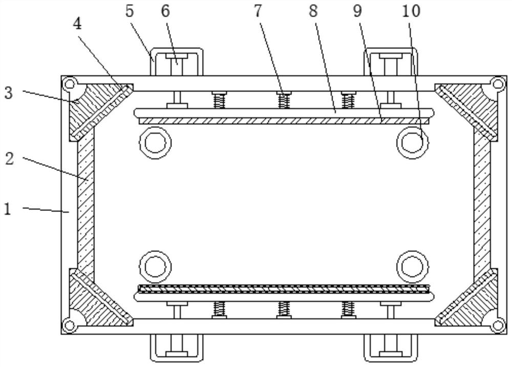
[0028] This embodiment provides a specific structure of a battery shock absorber for a new energy vehicle, such as figure 1 As shown, the device body 1 includes a frame-shaped structure with a hollow top, and the device body 1 is used to place the battery to achieve battery shock absorption, wherein,

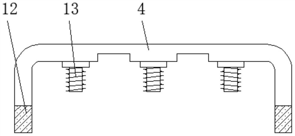
[0029] The inner walls at both ends of the device main body 1 are provided with elastic clip pads 2 , and the inner walls on both sides of the device main body 1 are provided with shock-absorbing splints 8 , which are connected by a primary shock-absorbing device 7 between the shock-absorbing splints 8 and the inner walls of the device main body 1 .

[0030] The primary damping device 7 adopts a spring structure or a shrapnel structure.

[0031] By adopting the above technical solutions:

[0032] When the battery of the new energy vehicle is installed inside the main body 1 of the device, it is clamped and fixed by the shock-absorbing splints 8 on both sides and the elastic cli...

Embodiment 2

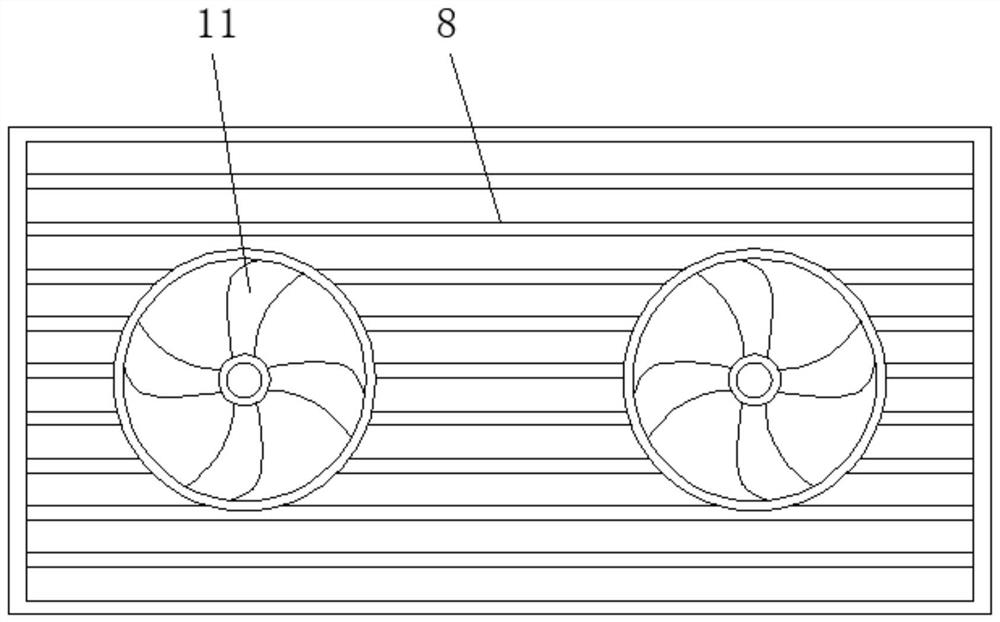
[0034] This embodiment provides a specific structure of a battery shock absorber for a new energy vehicle, such as figure 1 As shown in -2, the shock-absorbing splint 8 adopts a mesh structure, and the surface of the shock-absorbing splint 8 is covered with an elastic mesh pad 9. The shock-absorbing splint 8 is also embedded with a cooling fan 11. The main body of the device 1 is located at the same level as the cooling fan 11. A cooling through hole is provided.

[0035] Outer frames 5 are arranged on both sides of the outer walls of the main body 1 of the device, and a secondary damping device 6 is arranged inside the outer frame 5 .

[0036] By adopting the above technical solutions:

[0037] Since the shock-absorbing splint 8 adopts a mesh structure, the surface of the shock-absorbing splint 8 is covered with an elastic mesh pad 9. On the one hand, it can effectively prevent the battery from being in contact with the shock-absorbing splint 8 for a long time and cause seri...

Embodiment 3

[0039] This embodiment provides a specific structure of a battery shock absorber for a new energy vehicle, such as Figure 4 As shown, the secondary shock absorbing device 6 includes an air pressure tube 603 and a piston rod 604 sleeved at one end of the air pressure tube 603. The end of the piston rod 604 located inside the air pressure tube 603 is provided with a piston 602, and the other end of the piston rod 604 passes through the device. The outer wall of the main body 1 is fixed on the shock-absorbing splint 8 , and one side of the air pressure tube 603 is provided with a valve mouth 601 that can inflate or deflate the air pressure tube 603 .

[0040] By adopting the above technical solutions:

[0041] Inflate or deflate the inside of the air pressure tube 603 through the valve nozzle 601, so that the gas inside the air pressure tube 603 is provided to the piston 602 to become larger or smaller, so that the top pressure provided by the secondary shock absorber 6 to the s...


PUM


Abstract

The invention discloses a battery damping device for a new energy automobile. The device comprises a frame-shaped structure device main body with a hollow top, wherein the device main body is used forplacing a battery to achieve battery damping, elastic clamping pads are arranged on inner walls of two ends of the device main body, damping clamping plates are arranged on inner walls of two sides of the device main body, and the damping clamping plates are connected with the inner wall of the device main body through first-stage damping devices. The device is advantaged in that damping of a newenergy automobile battery is referred to, the elastic clamping pads are arranged on the inner walls of the two ends of the device body, the damping clamping plates are arranged on the inner walls ofthe two sides of the device body, in this way, after a battery is installed in the device body, the damping clamping plates on the two sides and the elastic clamping pads at the two ends clamp and fixthe battery, when a vehicle body vibrates, the damping effect can be effectively achieved due to the elastic effect of the first-stage damping device and the elastic clamping pads, and the battery isprotected.

Description

technical field [0001] The invention belongs to the technical field of new energy vehicles, in particular to a battery shock absorber for new energy vehicles. Background technique [0002] New energy vehicles refer to the use of unconventional vehicle fuels as power sources (or the use of conventional vehicle fuels, the use of new vehicle power devices), integrated vehicle power control and advanced technology in driving, the formation of advanced technical principles, with New technologies and new structures of vehicles, new energy vehicles include four types of hybrid electric vehicles (HEV), pure electric vehicles (BEV, including solar vehicles), fuel cell electric vehicles (FCEV), other new energy sources (such as supercapacitors, Flywheel and other high-efficiency energy storage) automobiles, etc., to promote new energy vehicles is to meet the needs of environmental protection and the oil crisis, reduce or abandon the current mainstream models that burn traditional gaso...

Claims


Application Information

Patent Timeline
Patent Type & Authority Patents(China)
IPC IPC(8): H01M2/10H01M10/613H01M10/625H01M10/6563
CPCH01M10/613H01M10/625H01M10/6563H01M50/20Y02E60/10Y02T10/62
Inventor 殷迎姣梅梅
Owner 梅梅
Why Eureka
Try Eureka