USB interface structure and electronic equipment

A technology of USB interface and connection terminal, which is applied in the field of USB interface structure and electronic equipment, can solve the problems of difficult processing, non-waterproof, complex structure, etc., and achieve the effect of simplifying the structure and facilitating processing

Pending Publication Date: 2020-02-11
SHANGHAI LONGCHEER TECH CO LTD
View PDF2 Cites 0 Cited by
  • Summary
  • Abstract
  • Description
  • Claims
  • Application Information

AI Technical Summary

Problems solved by technology

The invention patent with the authorized announcement number CN203932383U discloses a new type of Micro USB 5 PIN connector, and a connector with good stability and easy production is designed, but the structure of this connector is complicated, and the pins are directly inserted into the circuit board, not waterproof
The invention patent with the authorized notification number CN207517003U discloses a Type-C structure. In the Type-C structure, the injection molded pieces connected as a whole are designed, which reduces the possibility of the injection molded pieces being tilted as a whole and ensures the stability of the overall structure. , but in this structure, the metal sheet is fixedly connected to the circuit board, which brings great difficulty to processing due to the small size of the metal sheet

Method used


Image

  • USB interface structure and electronic equipment
  • USB interface structure and electronic equipment
  • USB interface structure and electronic equipment

Examples


Embodiment 1

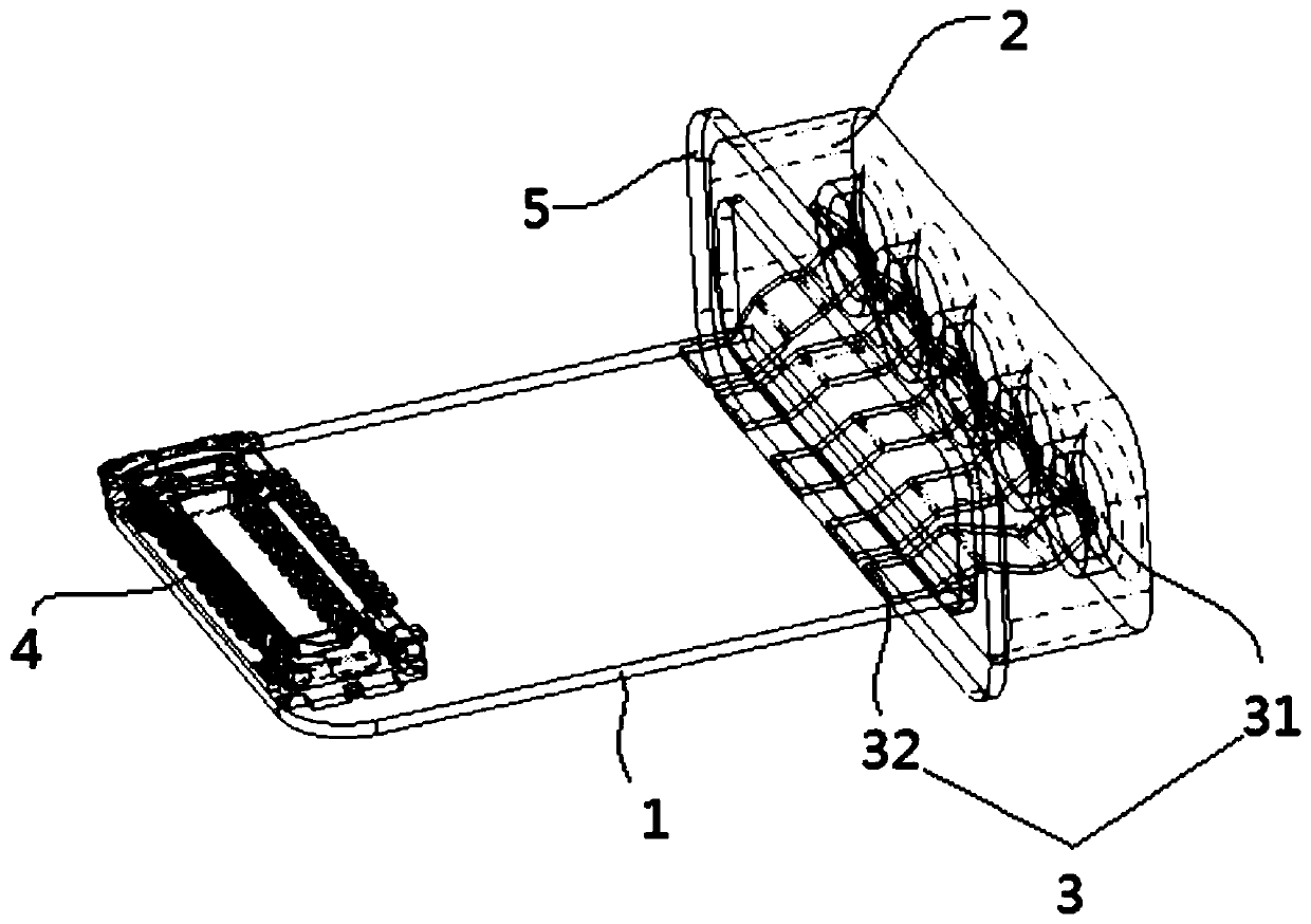
[0025] Such as figure 1 , figure 2 with image 3 As shown, a USB interface structure includes FPC1, plastic shell 2 and five connection terminals 3.

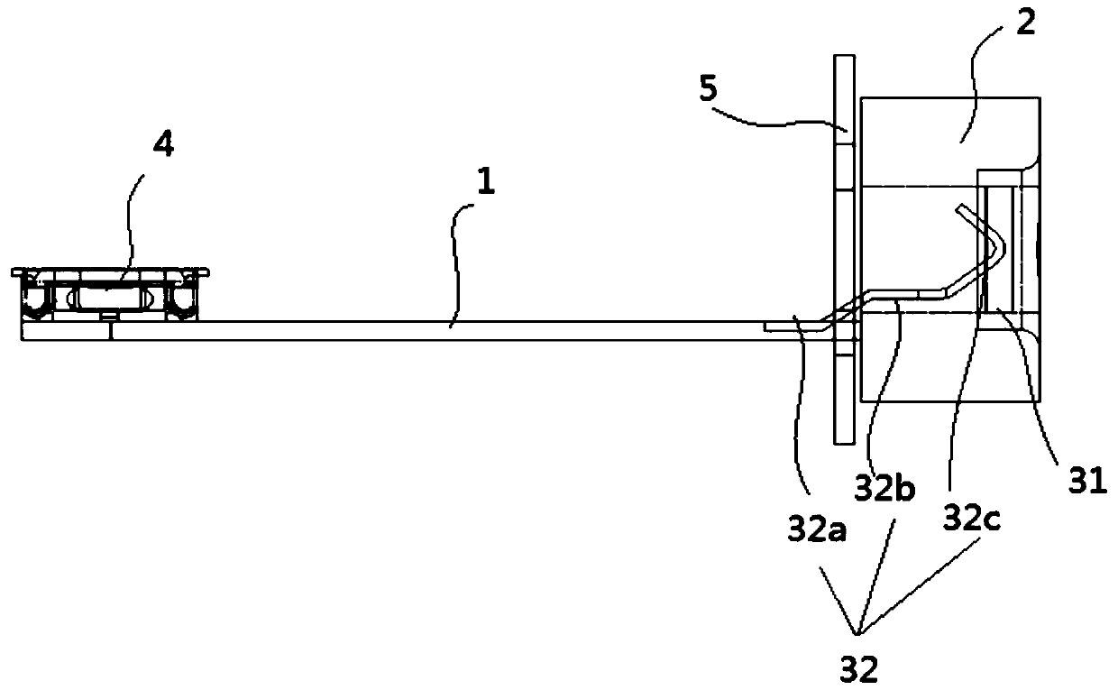
[0026] The FPC1 is arranged outside the plastic housing 2, one end is connected to the part of the connection terminal 3 protruding from the plastic housing 2, and the other end is connected to the circuit board through BTB connectors 4 (Board-to-Board Connectors).

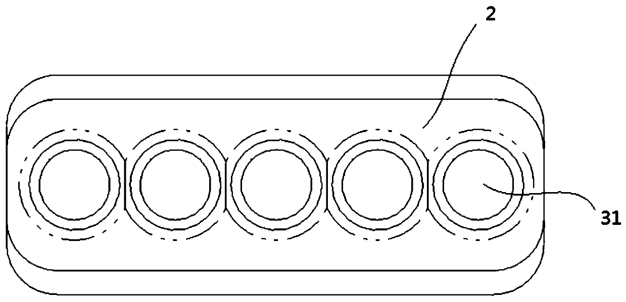
[0027] The plastic shell 2 is provided with five circular grooves for the insertion of the external connection end, and a cuboid-shaped accommodation cavity is provided inside, the grooves communicate with the inner cavity, and the plastic shell 2 is waterproof through The foam glue is connected with other structures of the electronic equipment, such as the casing of the electronic equipment;

[0028] The connection terminal 3 includes a contact piece 31 and an elastic piece 32 .

[0029] The contact piece 31 is arranged in the groove, and the contact piece 31 ...

Embodiment 2

[0033] Embodiment 2 is a modified form of Embodiment 1, and the difference between Embodiment 2 and Embodiment 1 is: as Figure 4 As shown, the groove in the embodiment 2 is a square, and the contact 31 includes a square bottom plate and a square tube-shaped side wall, and the connection between the side wall and the bottom plate is square cup-shaped, and the groove Shaped to match the square cup shape.

Embodiment 3

[0035] The embodiment 3 is a modified form of the embodiment 1, and the difference between the embodiment 3 and the embodiment 1 is that the contact piece 31 and the elastic piece 32 are integrally formed.

[0036] Advantages of the implementation of the present invention: the present invention provides a USB interface structure and electronic equipment, the USB interface structure includes an FPC, a plastic housing and at least two connection terminals, the FPC is arranged outside the plastic housing, It is used to connect the connection terminal and the circuit board; the plastic shell is provided with a groove for inserting the external connection end; the connection terminal includes a contact piece and a shrapnel, and the contact piece is arranged in the groove and connected to the The groove is sealed and connected, and the elastic piece is arranged between the contact piece and the FPC, and is electrically connected with the contact piece and the FPC. Through the above t...


PUM


Abstract

The invention provides a USB interface structure and electronic equipment. The USB interface structure comprises an FPC, a plastic shell and at least two connecting terminals. The FPC is arranged outside the plastic shell and is used for connecting the connecting terminals and a circuit board. The plastic shell is provided with a groove into which an external connecting end is inserted. Each connecting terminal comprises a contact piece and an elastic piece. The contact piece is arranged in the groove and is connected with the groove in a sealed mode, and the elastic piece is arranged betweenthe contact piece and the FPC and is electrically connected with the contact piece and the FPC. Through the technical scheme, a waterproof effect can be achieved, the structure of a USB interface canbe simplified, and the USB interface can be conveniently processed.

Description

technical field [0001] The invention relates to signal input / output equipment, in particular to a USB interface structure and electronic equipment. Background technique [0002] The USB interface is a connection structure frequently used in current electronic devices, and is used to implement a signal input or / output function. The invention patent with the authorized announcement number CN203932383U discloses a new type of Micro USB 5 PIN connector, and a connector with good stability and easy production is designed, but the structure of this connector is complicated, and the pins are directly inserted into the circuit board, not waterproof. The invention patent with the authorized notification number CN207517003U discloses a Type-C structure. In the Type-C structure, the injection molded pieces connected as a whole are designed, which reduces the possibility of the injection molded pieces being tilted as a whole and ensures the stability of the overall structure. , but in...

Claims


Application Information

Patent Timeline
IPC IPC(8): H01R12/77H01R13/02H01R4/48H01R13/52H01R12/79
CPCH01R4/4809H01R12/77H01R12/79H01R13/02H01R13/52H01R13/521
Inventor 王旭杜军红汤肖迅
Owner SHANGHAI LONGCHEER TECH CO LTD
Why Eureka
Try Eureka