
A mold for bending machine capable of changing any bending angle

A bending machine and mold technology, applied in the field of bending machines, can solve the problems of manpower operation in the process of loading and unloading, reduce the working efficiency of bending machines, increase the labor intensity of workers, etc., so as to save disassembly time, fast fixing effect, The effect of reducing labor intensity

Active Publication Date: 2021-01-19
苏州巨隆金属制品有限公司
View PDF12 Cites 0 Cited by
  • Summary
  • Abstract
  • Description
  • Claims
  • Application Information

AI Technical Summary

Problems solved by technology

[0003] Most of the upper mold and lower mold on the bending machine are fixed in shape, which leads to the fixed bending angle of the upper mold and the lower mold, and the bending angle cannot be changed. When the bending angle needs to be changed, only the upper mold and the lower mold can be loaded and unloaded. , the process is cumbersome, and the loading and unloading process is time-consuming. The loading and unloading process requires manual operation, and the labor load is large, which increases the labor intensity of the workers and reduces the work efficiency of the bending machine. Prepare multiple sets of upper and lower molds, which increases production costs

Method used


Image

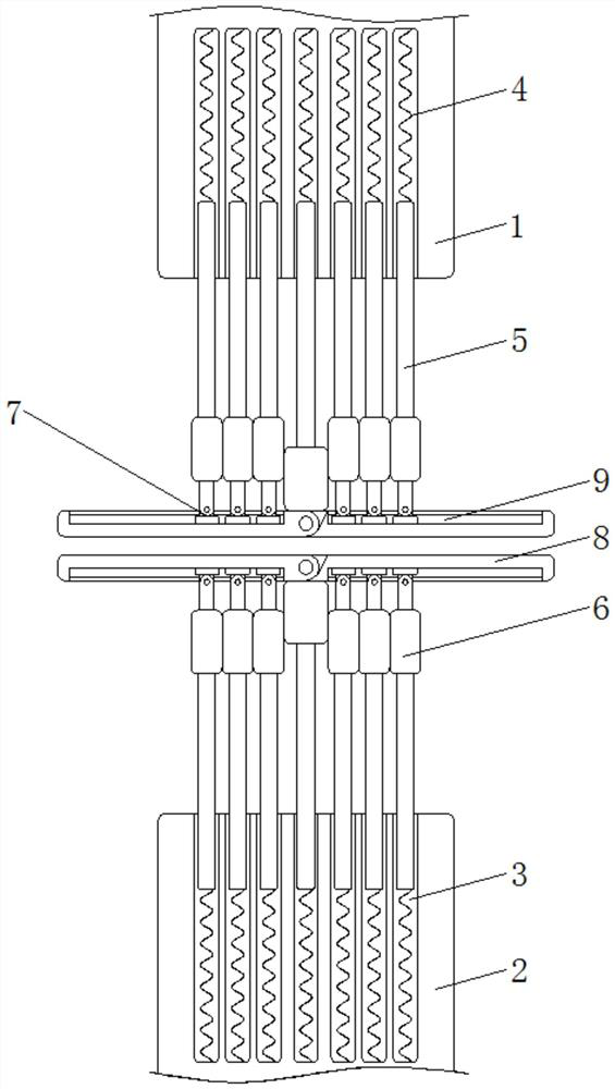
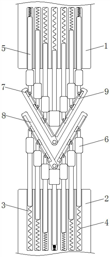
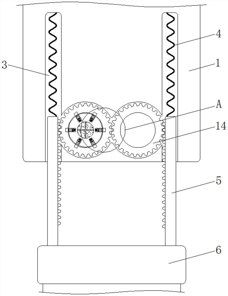
  • A mold for bending machine capable of changing any bending angle
  • A mold for bending machine capable of changing any bending angle
  • A mold for bending machine capable of changing any bending angle

Examples


Embodiment Construction

[0019] The following will clearly and completely describe the technical solutions in the embodiments of the present invention with reference to the accompanying drawings in the embodiments of the present invention. Obviously, the described embodiments are only some, not all, embodiments of the present invention. Based on the embodiments of the present invention, all other embodiments obtained by persons of ordinary skill in the art without making creative efforts belong to the protection scope of the present invention.

[0020] see Figure 1-4 , a die for a bending machine that can change any bending angle, including an upper die 1 and a lower die 2, the upper die 1 and the lower die 2 play the role of fixing each part, and the material of the upper die 1 and the lower die 2 is made of steel material and the shape of the upper mold 1 and the lower mold 2 is a cuboid, the length of the telescopic groove 3 is greater than the length of the gear bar 5 and the size of the telescop...


PUM


Abstract

A die for a bending machine that can change any bending angle, relates to the technical field of bending machines, and includes an upper die and a lower die. The middle parts of the upper die and the lower die are provided with evenly distributed telescopic grooves, and the bottom of the telescopic grooves is fixed Connected with spring one. The mold for bending machine that can change any bending angle is used through the cooperation of the gear bar and the pressure plate. When using it, first take a sample and place it between the upper mold and the lower mold, so that the corner tip of the plate is facing downward and not in contact with the lower mold. In the middle of the pressing plate, the upper mold and the lower mold are moved towards each other. Since the gear bar is elastically connected with the spring, the gear bar can be adjusted up and down, and because the pressing plate can rotate, the pressing plate will follow the movement of the upper mold and the lower mold. Gradually rotate, and finally make the pressing plate rotate to the same angle as the sample, so as to achieve the effect of changing the bending angle. The operation is simple and there is no need to disassemble the upper and lower dies, which saves disassembly time, improves production efficiency, and reduces workers' labor costs. Labor intensity.

Description

technical field [0001] The invention relates to the technical field of bending machines, in particular to a mold for bending machines capable of changing any bending angle. Background technique [0002] The bending machine is often used in sheet metal processing. The cut sheet needs to be folded into a certain angle before it can be put into use. At this time, it is necessary to use the bending machine to bend the sheet into a specific angle for later use. [0003] Most of the upper mold and lower mold on the bending machine are fixed in shape, which leads to the fixed bending angle of the upper mold and the lower mold, and the bending angle cannot be changed. When the bending angle needs to be changed, only the upper mold and the lower mold can be loaded and unloaded. , the process is cumbersome, and the loading and unloading process is time-consuming. The loading and unloading process requires manual operation, and the labor load is large, which increases the labor intensi...

Claims


Application Information

Patent Timeline
Patent Type & Authority Patents(China)
IPC IPC(8): B21D37/10B21D37/12B21D37/04B21D37/01
CPCB21D37/10B21D37/12B21D37/04B21D37/01
Inventor 蒋旭野
Owner 苏州巨隆金属制品有限公司
Learn More