Hardware mold cutting machine

A cutting machine and mold technology, applied in the direction of shearing equipment, cutting devices, manufacturing tools, etc., can solve problems such as trouble, low cutting effect, and inability to adjust the cutting size, so as to achieve thorough cutting and the best cutting effect , the effect of preventing adhesion

Inactive Publication Date: 2020-02-14
江门市健锋五金厂有限公司
View PDF0 Cites 0 Cited by
  • Summary
  • Abstract
  • Description
  • Claims
  • Application Information

AI Technical Summary

Problems solved by technology

[0002] Many hardware decorations nowadays often need to cut the hardware to make various patterns for decoration, but some hardware cutting machines installed on some hardware molds currently have cutting effects It is low, and the size of the cutting cannot be adjusted, which brings a lot of troubles to the later hardware production. Therefore, a hardware mold cutting machine is designed here, which can cut the hardware and automatically adjust the cutting according to the needs of the hardware. size

Method used


Image

  • Hardware mold cutting machine
  • Hardware mold cutting machine
  • Hardware mold cutting machine

Examples


Embodiment Construction

[0018] The following will clearly and completely describe the technical solutions in the embodiments of the present invention with reference to the accompanying drawings in the embodiments of the present invention. Obviously, the described embodiments are only some, not all, embodiments of the present invention. Based on the embodiments of the present invention, all other embodiments obtained by persons of ordinary skill in the art without making creative efforts belong to the protection scope of the present invention.

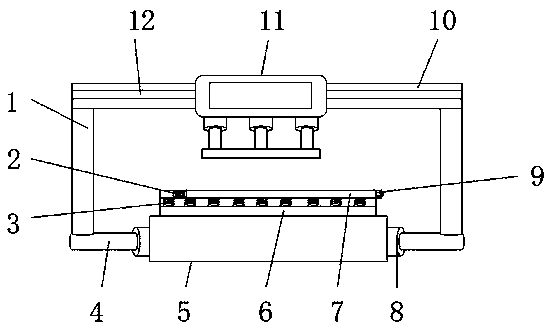
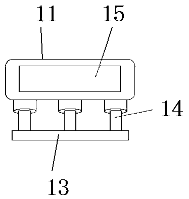
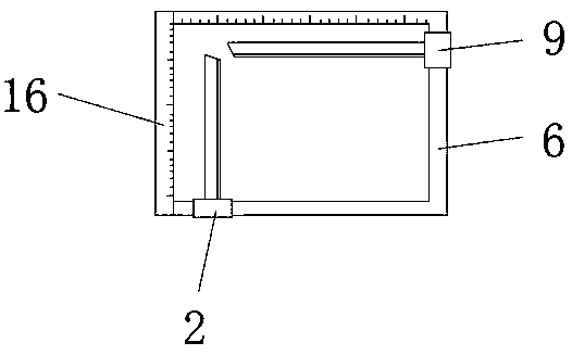
[0019] see Figure 1-4 , the present invention provides a technical solution: a metal mold cutting machine, including a hardware card box 5, the two ends of the hardware card box 5 are symmetrically installed with a rotating shaft 8, and one end of the rotating shaft 8 is rotatably installed with a support rod 4, supporting The upper ends of the rods 4 are all fixedly connected with the support column 1, and the upper end of the support column 1 is fixedly ins...


PUM


Abstract

The invention discloses a hardware mold cutting machine. The hardware mold cutting machine comprises a hardware clamping box, wherein rotating shafts are symmetrically mounted at two ends of the hardware clamping box; a supporting rod is rotatably mounted at one end of each rotating shaft; the upper end of each supporting rod is fixedly connected with a supporting column; a cross beam is fixedly mounted at the upper ends of the supporting columns; a track groove is formed in the cross beam; a shearing pressing plate is slidably mounted at the center end of the cross beam; a movable sliding block is fixedly mounted at the upper end of the shearing pressing plate; a hydraulic column is fixedly mounted at the lower end of the movable sliding block; a pressure plate is fixedly mounted at the lower end of the hydraulic column; a shearing adjusting plate is fixedly mounted at the upper end of the hardware clamping box; a chute is formed in the upper end of the shearing adjusting plate; a longitudinal shearing knife and a transverse shearing knife are slidably mounted in the chute; and shearing springs are separately mounted at the lower ends of the longitudinal shearing knife and the transverse shearing knife. By the hardware mold cutting machine, hardware can be quickly sheared as needed, and the shearing specification of the hardware can be adjusted.

Description

technical field [0001] The invention relates to the field of hardware mold equipment, in particular to a metal mold cutting machine. Background technique [0002] Many hardware decorations nowadays often need to cut the hardware to make various patterns for decoration, but some hardware cutting machines installed on some hardware molds currently have cutting effects It is low, and the size of the cutting cannot be adjusted, which brings a lot of troubles to the later hardware production. Therefore, a hardware mold cutting machine is designed here, which can cut the hardware and automatically adjust the cutting according to the needs of the hardware. size. Contents of the invention [0003] The object of the present invention is to provide a metal mold cutting machine to solve the problems raised in the above-mentioned background technology. [0004] In order to achieve the above object, the present invention provides the following technical solutions: a metal mold cuttin...

Claims


Application Information

Patent Timeline
Patent Type & Authority Applications(China)
IPC IPC(8): B23D31/00B23D33/02B23D33/00
CPCB23D31/00B23D31/002B23D33/00B23D33/02
Inventor 黄健勇
Owner 江门市健锋五金厂有限公司
Why Eureka
Try Eureka