
Pushing plate type scattering device

A throwing device and push plate technology, which is applied in the direction of launching devices, transportation and packaging, and equipment for loading and unloading goods, etc., can solve the problems of large space, unsuitable for tight space, low overload throwing, etc., and achieve high energy utilization rate , Reasonable structure design, low throwing overload effect

Pending Publication Date: 2020-02-14
HUNAN SHENFU GRP XIANGHONG MACHINERY CHEM
View PDF0 Cites 0 Cited by
  • Summary
  • Abstract
  • Description
  • Claims
  • Application Information

AI Technical Summary

Problems solved by technology

The airbag type flexible work throwing method is mainly used for the throwing work of multiple submunitions with enough space inside the aircraft submunition or in the circumferential direction, while the piston type work throwing method is generally suitable for throwing with large space and no special requirements for overload, and is not suitable for space. Tight, low-overload throwing

Method used


Image

  • Pushing plate type scattering device
  • Pushing plate type scattering device
  • Pushing plate type scattering device

Examples


Embodiment Construction

[0036] The specific implementation of the present invention will be further described below in conjunction with accompanying drawing:

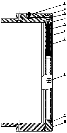
[0037] like figure 1 As shown, a push plate type throwing device includes: a fire contact part 1, a front end plate 2, a sealing screw 3, a fire transmission part 4, a gas generator 5, a push plate 6, a body 7, a pin seat 8, a tension Screw rod 9, rear end plate 10;

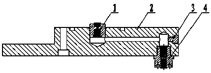
[0038] The threads of the fire-connecting part 1 and the fire-transmitting part 4 are glued and then screwed into the center screw hole on the upper end surface of the front end plate 2 and the outer screw hole on the lower end surface respectively;

[0039] The seal screw 3 thread is screwed into the screw hole on the outside of the front plate 2 after being glued;

[0040] The upper end thread of the gas generator 5 is glued and screwed to the output end of the fire transmission part 4;

[0041] The push plate 6 is connected to the body 7 through the longitudinal anastomosis...


PUM


Abstract

The invention discloses a pushing plate type scattering device. The device is mainly technically characterized by comprising a fire receiving part 1, a front end plate 2, a seal screw 3, a fire transmission part 4, a gas generator 5, a pushing plate 6, a body 7, a pin base 8, a tensioning screw rod 9 and a rear end plate 10. The fire receiving part 1 adopts a reverse closed air one-way fire transmission structure, a turning fire transmission channel is designed in the front end plate 2, the fire transmission part 4 transmits flame energy of the fire receiving part 1 to the gas generator, the gas generator 5 combusts to generate a large amount of high-temperature gas, the pushing plate 6 and the body 7 are of U groove structures, the pushing plate 6 and the body 7 are longitudinally matchedand inserted through V concave and convex grooves to form a primary seal containing cavity, the high-temperature gas generated by the gas generator 5 is filled in the seal containing cavity, expansion work is done to push the pushing plate to rapidly move, constraint is relieved, and bullet explosives are pushed out instantly. The device has the advantages of being reasonable in structure design,safe and reliable in use, suitable for batched production and the like.

Description

technical field [0001] The invention relates to a throwing device, in particular to a push-plate type throwing device with variable direction fire transmission and directional throwing, which belongs to the technical field of pyrotechnic devices, and is mainly suitable for throwing bullets of aircraft submunitions mounted on drones. Background technique [0002] With the rapid development of military technology, my country's status in the world's military powers has been continuously improved, especially in the field of unmanned aerial vehicles (UAVs). The sub-munition dispensing technology of aviation sub-bombs with various complex structures has ushered in rapid development. In the background technology, the existing domestic submunition throwing methods mainly include two kinds of throwing methods: airbag flexible work and piston work. The airbag type flexible work throwing method is mainly used for the throwing work of multiple submunitions with enough space inside the a...

Claims


Application Information

Patent Timeline
Patent Type & Authority Applications(China)
IPC IPC(8): B64D1/06B64D9/00
CPCB64D1/06B64D9/00
Inventor 刘志华戴东松易勇刘平彭渊李贤连欧海峰付展鹏周纳微付志斌
Owner HUNAN SHENFU GRP XIANGHONG MACHINERY CHEM
Learn More