Fixture for foaming of refrigerator box body

A box and fixture technology, which is applied in the field of fixtures for foaming refrigerator boxes, can solve problems such as difficulty in ensuring safety, work interference, and damage to foamed boxes

Active Publication Date: 2020-04-28
ANHUI KINGPOWER EQUIP & MOLD MFR
View PDF11 Cites 2 Cited by
  • Summary
  • Abstract
  • Description
  • Claims
  • Application Information

AI Technical Summary

Problems solved by technology

[0002] Most of the existing lifting transmission mechanisms for foaming fixtures use hydraulic equipment as their power system, which has the problems of slow lifting speed, large instantaneous impact force during the lifting process, and poor transmission accuracy and stability. The foam box causes damage, and when it is installed and matched with the external frame, the overall loading and unloading operation is too cumbersome, and the space for loading other components is small, which easily interferes with the work of each component;
[0003] The existing conveying mechanism for foaming fixtures only has a single conveying function, and cannot adjust the belt height for boxes with different shapes, which makes the compatibility and adaptability poor, and it is difficult to fit various processed products the actual needs of
[0004] Most of the existing side plate support pipe structures used for foaming fixtures are flat plates. Although the production and installation of flat plates are relatively simple, their stress conditions during use are poor. are affected;
[0005] Most of the existing locking mechanisms for foaming fixtures are equipped with ball screws. Although ball screws have small friction and smooth motion during motion, they do not have self-locking functions, and are prone to Th

Method used


Image

  • Fixture for foaming of refrigerator box body
  • Fixture for foaming of refrigerator box body
  • Fixture for foaming of refrigerator box body

Examples


Embodiment Construction

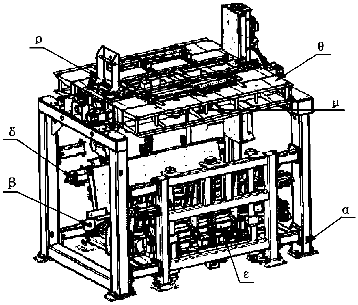
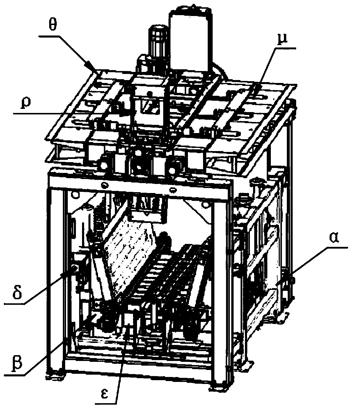
[0062] Such as Figure 1-17 As shown in Fig. 1, a fixture used for foaming refrigerator boxes, including lifting transmission mechanism α, belt conveying mechanism β, supporting pipe mechanism ε, locking mechanism δ, flip positioning mechanism θ, transmission limit mechanism μ and front baffle The limit mechanism ρ, the inside of the lifting transmission mechanism α is provided with a belt conveying mechanism β, the top of the belt conveying mechanism β is provided with a supporting pipe mechanism ε, and both sides of the lifting transmission mechanism α are correspondingly equipped with a locking mechanism δ, and the lifting transmission mechanism The center of the top of α is provided with an overturning positioning mechanism θ, and both sides of the overturning positioning mechanism θ are correspondingly provided with a transmission limiting mechanism μ, and the top and bottom of the overturning positioning mechanism θ are respectively provided with a front baffle limiting m...


PUM


Abstract

The invention discloses a fixture for foaming of a refrigerator box body. The fixture includes a lifting transmission mechanism, a belt conveying mechanism, a supporting pipe mechanism, locking mechanisms, a turnover positioning mechanism, transmission limiting mechanisms and front baffle limiting mechanisms. The lifting transmission mechanism is internally provided with the belt conveying mechanism. The supporting pipe mechanism is arranged at the top of the belt conveying mechanism. The locking mechanisms are arranged on two sides of the lifting transmission mechanism correspondingly. The turnover positioning mechanism is arranged at the center of the top of the lifting transmission mechanism. The transmission limiting mechanisms are arranged on two sides of the turnover positioning mechanism, and the front baffle limiting mechanisms are arranged at the top and the bottom of the turnover positioning mechanism correspondingly. The lifting transmission mechanism, the belt conveying mechanism, the supporting pipe mechanism, the locking mechanisms, the turnover positioning mechanism, the transmission limiting mechanisms and the front baffle limiting mechanisms are combined to improvethe overall production efficiency and automation.

Description

technical field [0001] The invention relates to the technical field of foaming fixtures, in particular to a fixture for foaming a refrigerator box. Background technique [0002] Most of the existing lifting transmission mechanisms for foaming fixtures use hydraulic equipment as their power system, which has the problems of slow lifting speed, large instantaneous impact force during the lifting process, and poor transmission accuracy and stability. The foam box causes damage, and when it is installed and matched with the external frame, the overall loading and unloading operation is too cumbersome, and the space for loading other components is small, which easily interferes with the work of each component; [0003] The existing conveying mechanism for foaming fixtures only has a single conveying function, and cannot adjust the belt height for boxes with different shapes, which makes the compatibility and adaptability poor, and it is difficult to fit various processed products...

Claims


Application Information

Patent Timeline
IPC IPC(8): B29C44/34
CPCB29C44/35
Inventor 孙敏钱思圣
Owner ANHUI KINGPOWER EQUIP & MOLD MFR
Why Eureka
Try Eureka