
Ice unloading device

A loading and unloading device and a technology of rotating fit, which is applied in the field of ice loading and unloading devices, can solve the problems of unfavorable access of large heavy industrial equipment, small loading and unloading places, and high labor costs, and achieve the effects of easy handling and operation, convenient operation, and reduced labor costs

Inactive Publication Date: 2020-02-14
ANHUI HUATENG AGRI TECH CO LTD
View PDF9 Cites 0 Cited by
  • Summary
  • Abstract
  • Description
  • Claims
  • Application Information

AI Technical Summary

Problems solved by technology

The use of large ice cubes is widely used in seafood, catering, hygiene, industry, etc. However, the loading and unloading of ice cubes is also a headache. The cost is high, the efficiency is low, and the heavy ice cubes are easy to make people feel tired, which is easy to cause safety hazards, and the loading and unloading places are relatively narrow, such as wine cellars, ice storages, etc., which are extremely unfavorable for large heavy industrial equipment to enter, such as many of the above The disadvantages are often criticized by people. In order to solve the above technical problems and achieve high efficiency, automation, safety and low cost of ice loading and unloading, the traditional device can no longer meet the needs of existing life and work. Therefore, it is necessary to design an easy-to-operate , a high degree of automation, low cost and safe ice loading and unloading device

Method used


Image

  • Ice unloading device
  • Ice unloading device
  • Ice unloading device

Examples


Embodiment Construction

[0016] Combine below Figure 1-3 The present invention is described in detail, wherein, for the convenience of description, the orientations mentioned below are defined as follows: figure 1 The up, down, left, right, front and back directions of the projection relationship itself are the same.

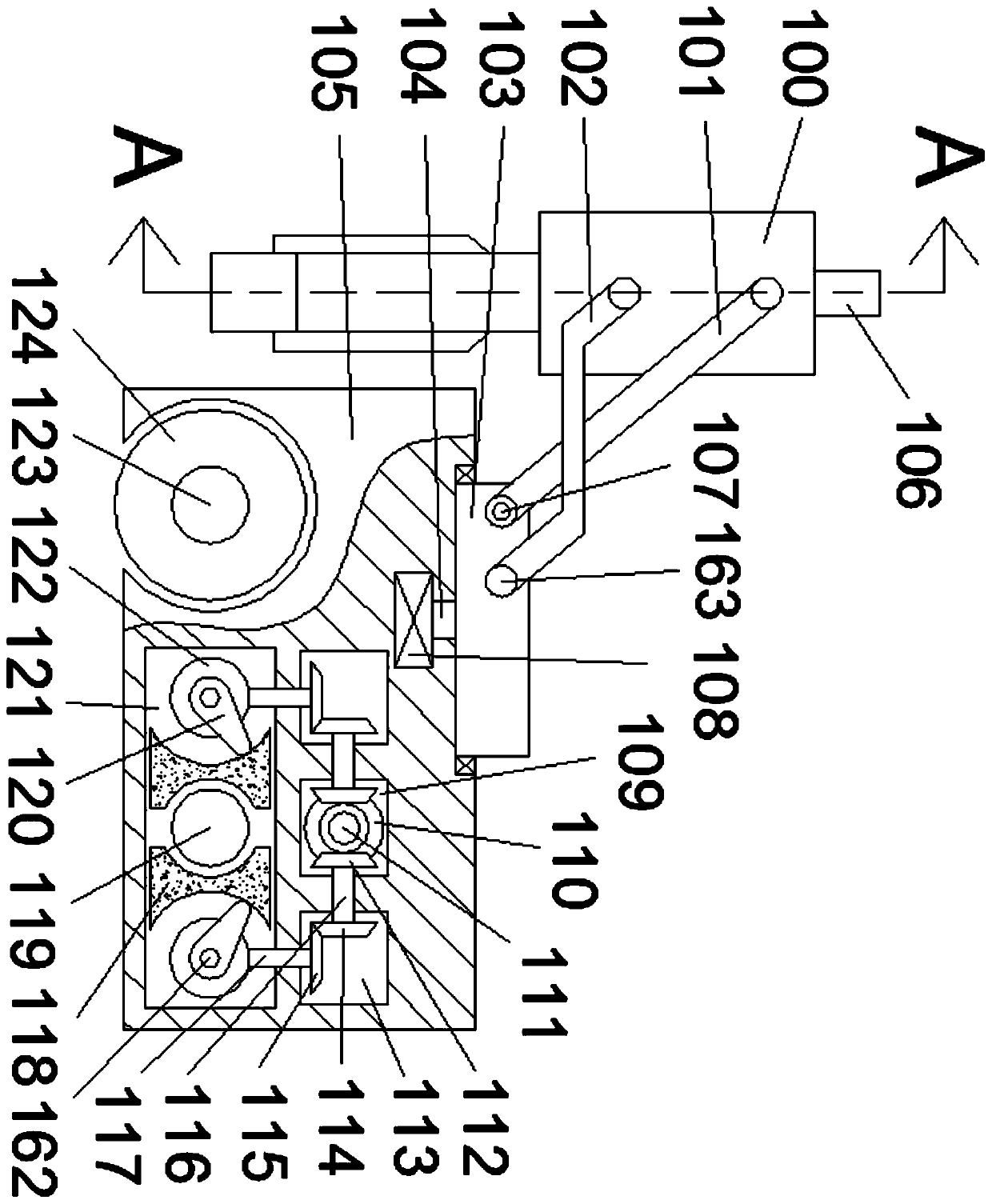
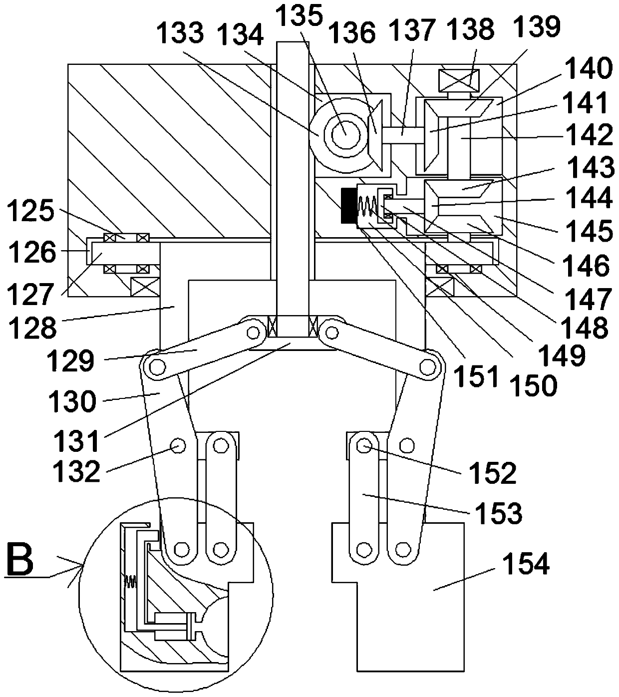
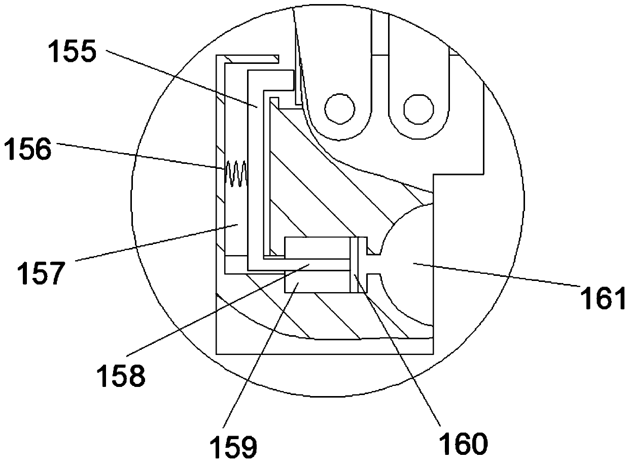
[0017] refer to Figure 1-3 , a kind of ice loading and unloading device of the present invention, comprises fuselage 105 and the front wheel rotating shaft 123 that is arranged in described fuselage 105 and extends back and forth, and described front wheel rotating shaft 123 is connected with front wheel 124 in rotation fit, and described The right side of the front wheel rotating shaft 123 is provided with a rear wheel rotating shaft brake chamber 121, and the rear wheel shaft locking assembly is arranged in the rear wheel rotating shaft braking chamber 121, and the rear wheel shaft locking assembly can make the whole device in the It can also be in the braking state in the crushed...


PUM


Abstract

The invention discloses an ice unloading device which comprises a device body and a front wheel rotating shaft extending in the device body in the front-back direction. The front wheel rotating shaftis rotationally matched and connected with a front wheel, and a rear wheel rotating shaft braking cavity is formed in the right side of the front wheel rotating shaft. A rear wheel axle locking assembly is arranged in the rear wheel rotating shaft braking cavity, and due to the rear wheel axle locking assembly, the whole device can also be in a braking state when being in a smashed ice environment. A synchronous gear engagement cavity is formed in the upper side of the rear wheel axle braking cavity, and a cam synchronous assembly is arranged in the synchronous gear engagement cavity. By meansof the ice unloading device, mechanical drive fit is achieved in the whole process, the rhythm is compact, matching is coherent, the work efficiency of the device is improved, design is small and exquisite, the ice unloading device is suitable for narrow-space operation, operation is easy and convenient, the automation degree is high, energy is saved, and a large amount of labor cost is further reduced.

Description

technical field [0001] The invention relates to the technical field of ice loading and unloading, in particular to an ice loading and unloading device. Background technique [0002] With the development of the domestic economy and the improvement of people's living standards, in the face of the scorching heat of summer, people respond in various ways, among which ice cubes cannot be forgotten by people. As we all know, ice cubes generally refer to liquid water. The solid water made after freezing is usually used to cool down or make ice drinks. Among them, industrial ice is also called large ice cubes, strip ice, ice bricks, etc. Ice is made by freezing pure tap water, and the temperature is about minus 20 degrees. The use of large ice cubes is widely used in seafood, catering, hygiene, industry, etc. However, the loading and unloading of ice cubes is also a headache. The cost is high, the efficiency is low, and the heavy ice cubes are easy to make people feel tired, which ...

Claims


Application Information

Patent Timeline
Patent Type & Authority Applications(China)
IPC IPC(8): B66F9/06B66F9/075B66F9/18B66F9/20
CPCB66F9/06B66F9/07572B66F9/18B66F9/20
Inventor 陈云侠
Owner ANHUI HUATENG AGRI TECH CO LTD
Learn More