
Photocatalytic reaction system for reducing pollutants in drainage pipe network

A technology of photocatalytic reaction and drainage pipe network, which is applied in the direction of waterway system, water/sewage treatment, light water/sewage treatment, etc., can solve the problems of single photocatalytic oxidation, neglect of direct photolysis and disinfection and sterilization, etc. Achieve the effect of easy implementation and promotion, high income and strong pertinence

Pending Publication Date: 2020-02-14
SHANGHAI MUNICIPAL ENG DESIGN INST GRP
View PDF0 Cites 2 Cited by
  • Summary
  • Abstract
  • Description
  • Claims
  • Application Information

AI Technical Summary

Problems solved by technology

[0013] However, most of the current photocatalytic oxidation technologies only focus on the synergistic effect of ultraviolet light and photocatalytic materials, but there are few studies or cases that take into account the disinfection and sterilization of ultraviolet lamps and direct photolysis in this process.
Most of the existing photocatalytic oxidation systems are limited to a single photocatalytic oxidation, but ignore the direct photolysis and disinfection of ultraviolet rays.

Method used


Image

  • Photocatalytic reaction system for reducing pollutants in drainage pipe network
  • Photocatalytic reaction system for reducing pollutants in drainage pipe network
  • Photocatalytic reaction system for reducing pollutants in drainage pipe network

Examples


Embodiment Construction

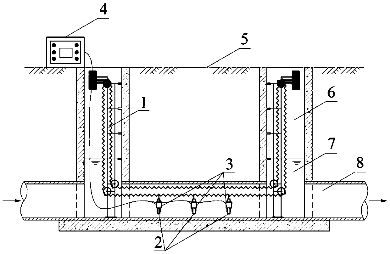
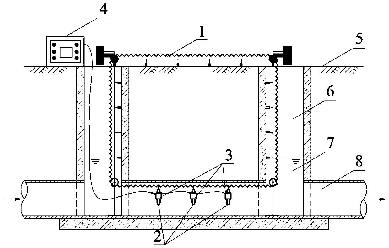
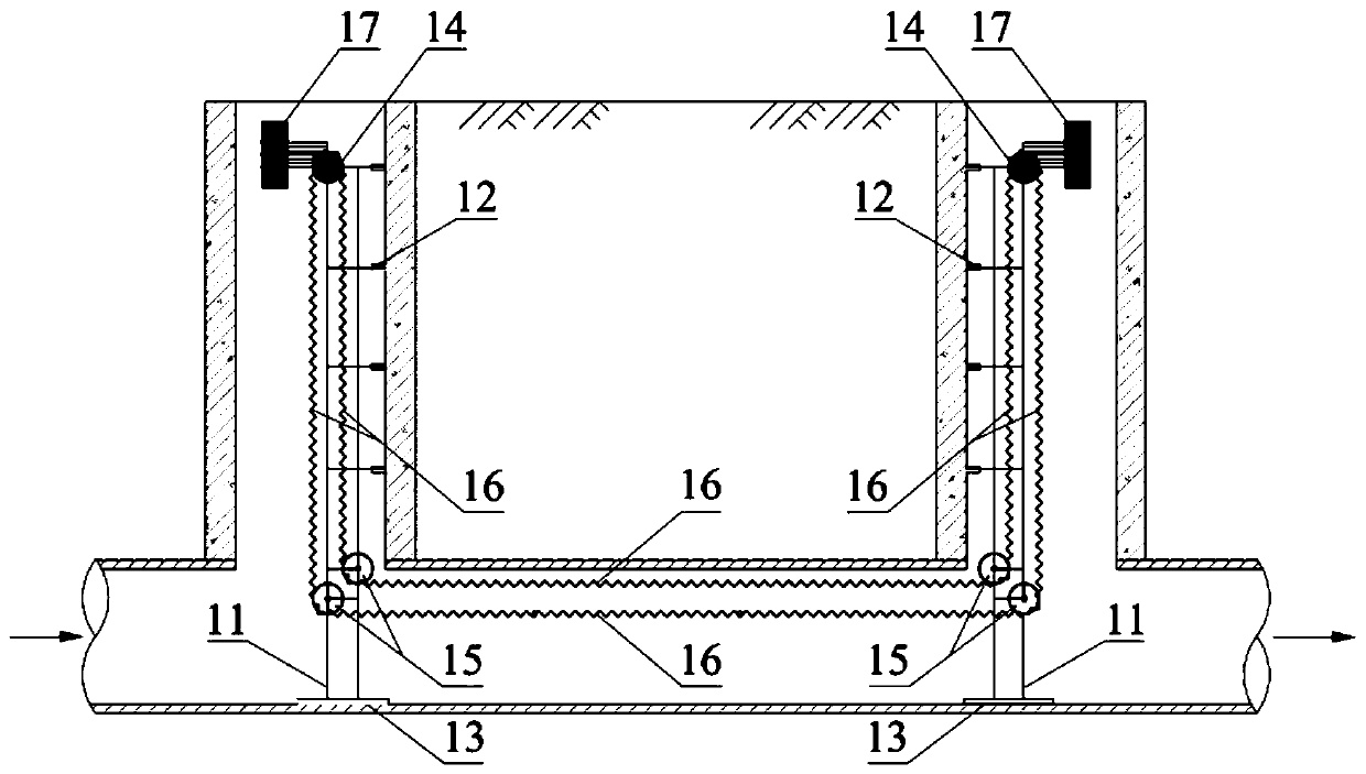
[0076] In conjunction with the following specific embodiments and accompanying drawings, the invention will be further described in detail. The process, conditions, experimental methods, etc. for implementing the present invention, except for the content specifically mentioned below, are common knowledge and common knowledge in this field, and the present invention has no special limitation content.

[0077] A photocatalytic reaction system for reducing pollutants in the drainage pipe network, characterized in that the purification system includes

[0078] A chain guide rail 1, the chain guide rail 1 is installed in the inspection well 6 and the drainage pipe 8;

[0079] Suspension bracket 2, the suspension bracket 2 is suspended on the chain guide rail 1;

[0080] A photocatalytic unit 3, the photocatalytic unit 3 is nested in the suspension bracket 2, moves along the chain guide rail 1 in the inspection well 6 and the drainage pipe 8, and is used for the in-situ water purif...


PUM

PropertyMeasurementUnit
lengthaaaaaaaaaa
thicknessaaaaaaaaaa
wavelengthaaaaaaaaaa

Abstract

The invention provides a photocatalytic reaction system for reducing pollutants in a drainage pipe network. The photocatalytic reaction system comprises chain type guide rails, a suspension type support, a photocatalysis unit and a power supply monitoring unit. The chain-type guide rails are installed in an inspection well and a drainage pipeline, the suspension type support is suspended on the chain-type guide rail, the photocatalysis unit is nested in the suspension type support, and the power supply monitoring unit supplies power to the photocatalysis unit and monitors operation conditionsof the photocatalysis unit. Furthermore, the invention further discloses an installation, operation and maintenance method of the system. According to the system and the method, the internal spaces ofthe inspection well and the drainage pipeline are fully utilized; conveying and arrangement of the photocatalysis unit in the drainage pipeline are achieved through ingenious design of the chain typeguide rails and the suspension type support, and in-situ water quality purification and disinfection and sterilization of the drainage pipeline are achieved through flexible switching of the functions of photocatalysis oxidation, direct photolysis, ultraviolet disinfection and the like of the photocatalysis unit. Compared with the prior art, the system has the outstanding characteristics of highapplicability, easiness in implementation, multiple functions, flexibility in operation, remarkable effect and the like.

Description

technical field [0001] The invention belongs to the technical field of municipal drainage, and in particular relates to a photocatalytic reaction system for reducing pollutants in drainage pipe networks. Background technique [0002] Drainage pipes are engineering facilities that collect and transport urban domestic sewage, industrial wastewater and rainwater. In recent years, with the acceleration of my country's urbanization process, the number and scale of construction of drainage pipes are also increasing year by year. For example: During the "13th Five-Year Plan" period, on the basis of the total length of about 9530km of drainage pipelines in Shanghai, about 100km of supporting drainage pipelines in the central urban area and about 310km of newly built drainage pipelines in the suburbs. The increasingly perfect drainage pipeline system provides convenience for the transportation of various types of sewage and rainwater in cities and towns. However, with the gradual ex...

Claims


Application Information

Patent Timeline
Patent Type & Authority Applications(China)
IPC IPC(8): C02F1/32C02F1/72E03F7/00
CPCC02F1/32C02F1/725E03F7/00C02F2307/08C02F2303/04C02F2201/322
Inventor 崔贺董磊张欣杨一烽
Owner SHANGHAI MUNICIPAL ENG DESIGN INST GRP
Learn More