Rail type in-situ purification system for water discharge pipeline

A technology for drainage pipelines and purification systems, applied in waterway systems, water supply devices, water treatment sites, etc., can solve problems such as affecting normal drainage, black and odorous sewage, and easy to block pipelines, achieving easy implementation and promotion, small investment scale, The effect of less engineering measures

Pending Publication Date: 2020-02-21
SHANGHAI MUNICIPAL ENG DESIGN INST GRP
View PDF0 Cites 7 Cited by
  • Summary
  • Abstract
  • Description
  • Claims
  • Application Information

AI Technical Summary

Problems solved by technology

[0003] These problems are mainly manifested in: 1) Harmful microorganisms (such as iron bacteria and sulfur bacteria) that grow in drainage pipes can easily cause corrosion and blockage of pipelines and related equipment; 2) Anaerobic hydrolysis of organic polluted wastewater in drainage pipes can produce a large amount of Toxic, flammable, explosive gases (such as: carbon monoxide (CO), hydrogen sulfide (H 2 S)), accumulation to a certain extent can cause poisoning or explosion in case of open fire; 3) Mosquitoes, flies, cockroaches and other vectors are easy to breed in drainage pipes or inspection wells, endangering human health; 4) If the drainage pipes have not been dredged for a long time, the Scum or sediment will easily block the pipeline and affect the normal drainage; 5) The lack of oxygen-enriched environment and aerobic microorganisms in the drainage pipeline will cause black and odorous sewage and a large amount of odor will escape from the inspection well, which will stimulate the public's senses
[0004] Faced with the above problems, the existing urban drainage pipeline system in my country still only has the capacity of transportation, but does not have the function of water purification.

Method used


Image

  • Rail type in-situ purification system for water discharge pipeline
  • Rail type in-situ purification system for water discharge pipeline
  • Rail type in-situ purification system for water discharge pipeline

Examples


Embodiment 1

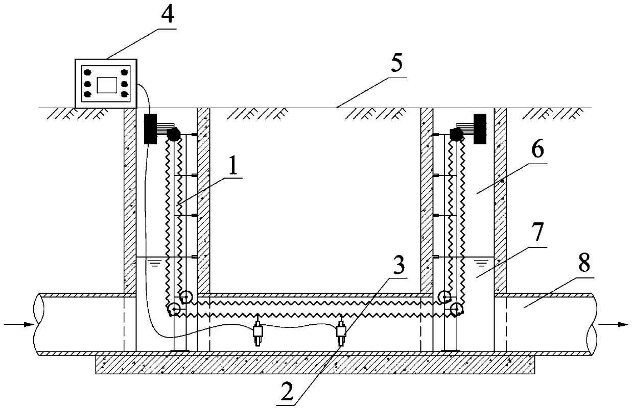
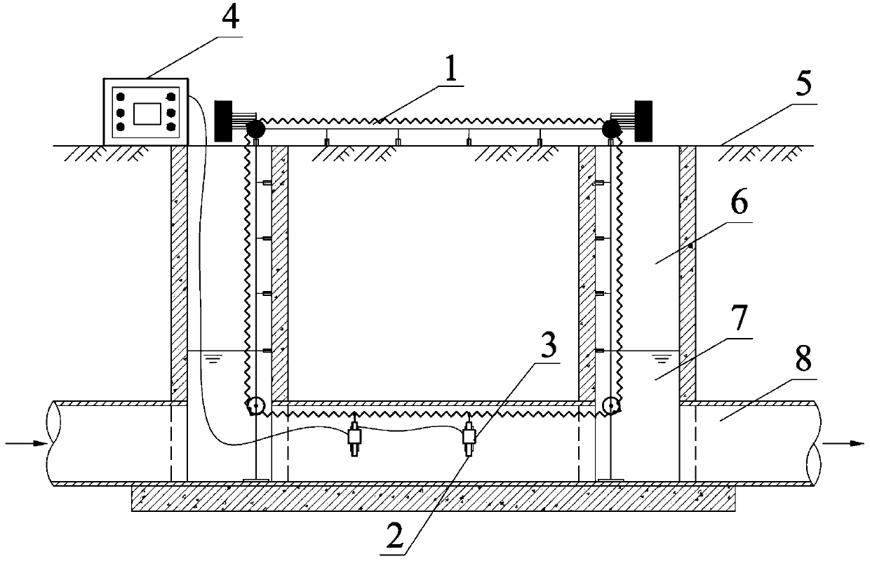
[0110] A track-type in-situ purification system for drainage pipes, the system specifically includes: a chain track 1, a suspension bracket 2, a processing unit 3 and an auxiliary unit 4; the chain track 1 is installed in the inspection well 6 and the drainage pipe 8 Inside, the suspension bracket 2 is suspended on the chain track 1 , and the processing unit 3 is nested in the suspension bracket 2 .

[0111] The suspension bracket 2 is composed of a hook 21, a frame body 22, a draw slot 23 and a counterweight 24; wherein, the hook 21 engages with the pin shaft of the chain 16, thereby limiting the frame body 22 and the The relative position of the chain 16; the hook 21 is set on the frame body 22, and the frame body 22 is provided with a card slot 23.

[0112] The processing unit 3 of the system selects an ultraviolet photodecomposer 31 , and correspondingly, the auxiliary unit 4 selects an ultraviolet sensing probe 41 .

[0113] The main body of the ultraviolet irradiation u...

Embodiment 2

[0135] The track-type in-situ purification system used for drainage pipes has the same basic structure and water purification method as in Example 1, the processing unit 3 is a photocatalytic unit 32, and the auxiliary unit 4 supplies power to the photocatalytic unit and monitors its operation in real time. The implementation method is:

[0136] The suspension bracket 2 is composed of a hook 21, a frame body 22, a card slot 23, a snap-on grid and a counterweight 24; wherein, the hook 21 is engaged with the pin shaft of the chain 16, thereby limiting the The relative position of the frame body 22 and the chain; the hook 21 is arranged on the frame body 22, and the card slot 23 is arranged on the frame body 22; the card slot 23 is located on the surface of the frame body 22 for nesting the Photocatalytic unit 32; the main body of the photocatalytic unit 32 is an ultraviolet lamp tube, and the end of the ultraviolet lamp tube is waterproof through a waterproof coating; the draw-i...

Embodiment 3

[0158] The track-type in-situ purification system for drainage pipes has the same basic structure and water purification method as in Embodiment 1, the processing unit 33 is an ultrasonic unit, and the auxiliary unit 4 is used to supply power to the ultrasonic unit 33 and regulate its vibration frequency and amplitude; Its specific implementation method is:

[0159]The suspension bracket is composed of a hook 21, a frame body 22, a draw-in groove 23 and a counterweight 24; wherein, the hook 21 passes through the pin shaft of the chain 16, thereby connecting the frame body 22 and the chain 16 Connected; the shape of the hook 21 is ring-shaped; the frame body 22 is connected to the hook 21, the card slot 23 is located on the surface of the frame body 22, and the ultrasonic unit 3 is embedded in the card slot 23; The counterweight 24 is located at the bottom of the frame body 22 and is used to increase the weight of the frame body 22 so that the suspension bracket 2 will not shak...


PUM

PropertyMeasurementUnit
lengthaaaaaaaaaa
thicknessaaaaaaaaaa
wavelengthaaaaaaaaaa

Abstract

The invention provides a rail type in-situ purification system for a water discharge pipeline. The rail type in-situ purification system comprises a chain type rail, a suspension type bracket, a processing unit and an auxiliary unit, wherein the chain type rail is installed in an inspection well and a water discharge pipeline, the suspension type bracket is suspended on the chain type rail, the processing unit is nested in the suspension type bracket, and the accessory unit is matched with the processing unit and assists the processing unit in normal operation. According to the invention, theinternal spaces of the inspection well and the water discharge pipeline are fully utilized, the conveying and arrangement of the processing unit in the water discharge pipeline can be realized throughthe ingenious design of the chain type rail and the suspension type bracket, and the in-situ water purification, disinfection sterilization and dredging of the water discharge pipeline are realized through the flexible combination of the processing unit and the auxiliary unit; and compared with the system in the prior art, the system of the invention has the outstanding characteristics of high applicability, easiness in implementation, multiple functions, flexibility in operation, remarkable effect and the like.

Description

technical field [0001] The invention belongs to the technical field of municipal drainage, and in particular relates to an orbital in-situ purification system for drainage pipes. Background technique [0002] Drainage pipes are engineering facilities that collect and transport urban domestic sewage, industrial wastewater and rainwater. In recent years, with the acceleration of my country's urbanization process, the number and scale of construction of drainage pipes are also increasing year by year. On the basis of the total length of about 9,530 km of drainage pipes in Shanghai, about 100 km of supporting drainage pipes in the central urban area and about 310 km of new drainage pipes in the suburbs. The increasingly perfect drainage pipeline system provides convenience for the transportation of various types of sewage and rainwater in cities and towns. However, with the gradual expansion of the drainage pipeline system, the problems of water quality pollution and secondary ...

Claims


Application Information

Patent Timeline
Patent Type & Authority Applications(China)
IPC IPC(8): C02F9/14E03F7/00
CPCC02F1/30C02F1/32C02F1/36C02F1/40C02F1/46104C02F1/66C02F1/725C02F3/00C02F3/34C02F9/00C02F2303/04C02F2307/08E03F7/00
Inventor 张欣董磊崔贺杨一烽
Owner SHANGHAI MUNICIPAL ENG DESIGN INST GRP
Why Eureka
Try Eureka