
Scramjet engine flow channel structure adopting center combustion and scramjet engine

A technology of scramjet and engine, which is applied in the direction of combustion chamber, combustion method, combustion equipment, etc., can solve the problem of not being able to balance the difficulty of low heat protection and high air utilization rate, and achieve the effect of excellent engine performance

Inactive Publication Date: 2020-02-14
BEIJING AEROSPACE TECH INST
View PDF8 Cites 5 Cited by
  • Summary
  • Abstract
  • Description
  • Claims
  • Application Information

AI Technical Summary

Problems solved by technology

[0004] The purpose of the present invention is to overcome the deficiencies in the prior art, to provide a scramjet flow channel configuration and a scramjet engine using central combustion, which can solve the difficulty of low heat protection that cannot be taken into account in the existing scramjet flow channel scheme and technical issues of high air utilization

Method used


Image

  • Scramjet engine flow channel structure adopting center combustion and scramjet engine
  • Scramjet engine flow channel structure adopting center combustion and scramjet engine
  • Scramjet engine flow channel structure adopting center combustion and scramjet engine

Examples


Embodiment Construction

[0025] It should be noted that, in the case of no conflict, the embodiments in the present application and the features in the embodiments can be combined with each other. The following will clearly and completely describe the technical solutions in the embodiments of the present invention with reference to the accompanying drawings in the embodiments of the present invention. Obviously, the described embodiments are only some, not all, embodiments of the present invention. The following description of at least one exemplary embodiment is merely illustrative in nature and in no way taken as limiting the invention, its application or uses. Based on the embodiments of the present invention, all other embodiments obtained by persons of ordinary skill in the art without creative efforts fall within the protection scope of the present invention.

[0026] It should be noted that the terminology used here is only for describing specific implementations, and is not intended to limit t...


PUM


Abstract

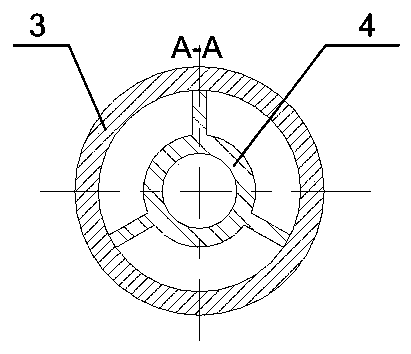
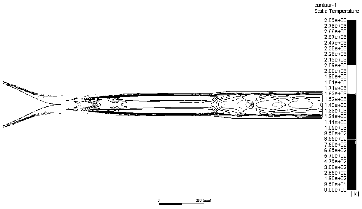
The invention provides a scramjet engine flow channel structure adopting center combustion and a scramjet engine. The flow channel structure design comprises a support plate injector, a gas inlet flowchannel and a combustion chamber flow channel, wherein the gas inlet flow channel and the combustion chamber flow channel are connected in a smooth transition manner in the flow incoming direction. The support plate ejector is arranged in the combustion chamber flow channel. The axis of the support plate injector coincides with the axis of the combustion chamber flow channel. In the direction ofthe axis of the support plate injector, the cross section of the support plate injector is in an annular shape. By means of the scheme, the technical problem that the low heat protection difficulty and the high air utilization rate cannot be considered at the same time in an existing scramjet engine flow channel scheme can be solved.

Description

technical field [0001] The invention relates to the technical field of scramjet engines, in particular to a scramjet runner configuration and a scramjet engine adopting central combustion. Background technique [0002] The scramjet engine is one of the main candidate powers for future near space vehicles, and it is also an important part of the combined engine for near space and aerospace flight. Since the middle of the last century, various scramjet flow channel schemes have been developed at home and abroad Design, regardless of whether the cross-section of the engine flow passage is rectangular or circular, the fuel injector and flame stabilizer usually includes a cavity, step or slope arranged on the wall surface and a support plate fixed to the wall surface and inserted into the flow passage. When structures such as concave cavity, support plate or slope are used, the combustion will mainly occur near the wall surface, resulting in great difficulty in thermal protection...

Claims


Application Information

Patent Timeline
IPC IPC(8): F23R3/28F23R3/42
CPCF23R3/28F23R3/42
Inventor 谢宗齐尹志仁汪颖向安定邵文清于鹏张原实张聪石峰梁磊
Owner BEIJING AEROSPACE TECH INST
Learn More