Charging control method and device

A charge control method and charge control technology, applied to circuit devices, battery circuit devices, secondary battery charging/discharging, etc., to achieve the effect of lowering temperature and reducing heat generation

Pending Publication Date: 2020-02-14
XIAN ZHONGXING NEW SOFTWARE
0 Cites 0 Cited by

AI-Extracted Technical Summary

Problems solved by technology

[0002] At present, mobile terminals with wireless charging h...

Method used

2. On the basis of the existing wireless charging temperature control scheme, on the hardware, a temperature sensor is added above the center of the cell in the battery below the center of the wireless charging coil of the mobile terminal, and a suitable software temperature control algorithm is used to solve the problem of wireless charging Compared with other technologies, the battery bulging problem caused by the rapid temperature rise of the battery cell caused by the heating of the coil is simpler and cost-saving.
[0079] In this embodiment, different control strategies are adopted according to whether t...

Abstract

The embodiment of the invention discloses a charging control method and device and a mobile terminal. The charging control method comprises the steps of detecting a charging mode; judging whether an application runs in the system or not when it is detected that the charging mode is wireless charging; determining a wireless charging current value according to the judgment result; and wirelessly charging a battery of the mobile terminal according to the determined wireless charging current value.

Application Domain

Technology Topic

Image

  • Charging control method and device
  • Charging control method and device
  • Charging control method and device

Examples

  • Experimental program(1)

Example Embodiment

[0067] In order to better explain the present invention, the current charging technology is first introduced below.
[0068] Low-power wireless charging (receiving end power less than 5W) due to the slow charging rate and poor user experience, has gradually withdrawn from the market. The latest standard of the Wireless Charging Standard (QI) introduces medium-power wireless charging with a receiving end power greater than 5W and less than 15W, and this increase in power will be accompanied by serious heating problems in practical applications.
[0069] When researching 5 to 15W wireless charging products, it was found that the charging efficiency of the wireless charging terminal is higher only when the center point of the wireless charging plate is located, the charging efficiency is about 70%, the heat generation is relatively small, and the offset center point is large. In order to ensure that the input power of the receiving end remains unchanged, the transmitting end often transmits with a higher power. At this time, the charging efficiency is less than 50%, and the large current passing through the transmitting end coil causes a lot of heat.
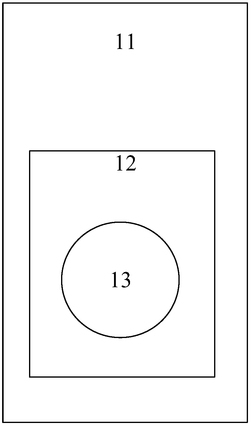
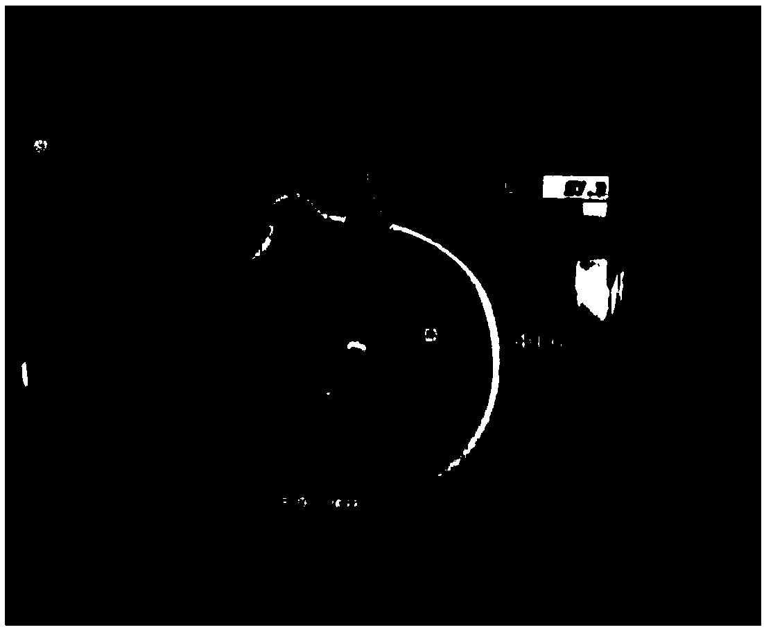
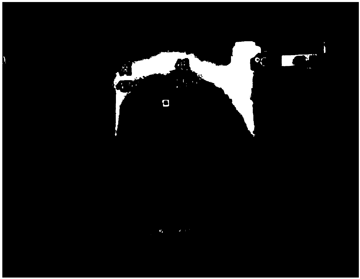
[0070] When researching wireless charging products below 5W, it is also found that the heat is very serious when the output current is large. Due to structural problems, such as figure 1 The position diagram of the wireless charging coil shown on the front of the whole machine (also called TOP side), figure 1 Among them, 11 is the rear case, 12 is the battery, and 13 is the wireless charging coil. At present, the wireless charging coils of all mobile terminals with wireless charging are located above the cell position on the back of the mobile terminal battery. In the test, the surface of the wireless charger and the contact surface of the mobile phone can reach more than 55 degrees. Such as Figure 2 to Figure 4 As shown, when the output current is 1A, check the battery negative temperature coefficient (NTC, Negative Temperature Coefficient) temperature (the battery NTC on the battery protection board) has reached 50 degrees in about an hour, and the wireless charger coil surface has reached 56 degrees , And the battery is under the wireless charger coil, that is to say, the temperature of the battery core is actually higher than the temperature of the NTC on the battery protection board at this time, so long-term charging may cause the battery to swell and affect the battery life. The product has the problem that the front panel is stretched due to the battery bulge caused by the wireless charging problem, and there is also a big safety risk. Therefore, the heating problem of wireless charging has become a major obstacle restricting the development of wireless charging, and how to solve the safety problem caused by the heating of wireless charging is the focus of current terminal research.
[0071] Based on this, the embodiment of the present invention proposes a charging control method and device, and a mobile terminal to solve the problem caused by wireless charging heating.
[0072] The technical solution of the present invention will be further described in detail below in conjunction with the drawings and specific embodiments.
[0073] The embodiment of the present invention provides a charging control method, which is applied to a mobile terminal, such as Figure 5 As shown, the method mainly includes:
[0074] Step 501: Detect whether the charging mode is wired charging or wireless charging.
[0075] Wherein, the wired charging can be understood as charging the mobile terminal through a USB cable.
[0076] It should be noted that in this embodiment, the mobile terminal supports both wired charging and wireless charging.
[0077] Step 502: When it is detected that it is wireless charging, it is determined whether there is an application running in the system.
[0078] In other words, when charging a mobile terminal, there may or may not be an application running in the system.
[0079] In this embodiment, different control strategies are adopted according to whether the system is running or not, so as to help determine a more appropriate wireless charging current value and facilitate subsequent timely adjustment of the wireless charging current value.
[0080] Step 503: Determine the wireless charging current value according to the judgment result.
[0081] In some optional implementation manners, the determining the wireless charging current value according to the judgment result includes:
[0082] When the judgment result is that no application is running in the system,
[0083] Acquiring the temperature value detected by the first temperature sensor, where the first temperature sensor collects the temperature of the center of the battery;
[0084] When it is detected that the temperature value does not exceed the first preset temperature threshold value, determining to charge the battery with the first wireless charging current value;
[0085] When it is detected that the temperature value exceeds the first preset temperature threshold value, it is determined to charge the battery with the second wireless charging current value; wherein, the first temperature sensor collects the temperature of the battery center, and the second wireless charging The current value is less than the first wireless charging current value.
[0086] Specifically, the first temperature sensor collects the temperature of the battery cell on the wireless charging coil.
[0087] Preferably, the first temperature sensor is located at the central position of the negative (also called BOT surface) on the wireless charging coil and placed next to the battery cell, and the first temperature sensor is used to detect the temperature of the battery cell during wireless charging.
[0088] Here, the first preset temperature threshold is the temperature at which there is a risk of battery bulging when the wireless charging coil heats up to the battery when the system is not applied during the wireless charging process.
[0089] Here, the first preset temperature threshold can be set or adjusted according to the battery model and/or type.
[0090] In some optional implementation manners, the determining the wireless charging current value according to the judgment result includes:
[0091] When the judgment result is that the system has applications running,
[0092] It is determined whether the temperature value of the first temperature sensor is higher than the temperature value of the second temperature sensor, and whether the temperature value of the second temperature sensor is higher than the second preset temperature threshold value, wherein the second temperature sensor collects the battery edge temperature;
[0093] If the temperature value of the first temperature sensor is higher than the temperature value of the second temperature sensor, and the temperature value of the second temperature sensor is higher than the second preset temperature threshold, it is determined that the battery is charged with the third wireless charging current value. Charge
[0094] Otherwise, it is determined to charge the battery of the mobile terminal with the fourth wireless charging current value while supplying power to the application; wherein the third wireless charging current value is less than the fourth wireless charging current value.
[0095] The second temperature sensor is located on the battery protection board, and the second temperature sensor collects the temperature of the battery edge close to the battery protection board.
[0096] Here, the second preset temperature threshold is the temperature value for starting the battery preset algorithm such as the JEITA algorithm on the battery protection board.
[0097] Here, the second preset temperature threshold may also be set or adjusted according to the battery model and/or type.
[0098] Further, when it is determined to charge the battery with the third wireless charging current value, the method further includes:
[0099] Detecting whether the temperature value of the first temperature sensor is higher than the third preset temperature threshold;
[0100] If it is higher than the third preset temperature threshold, it is determined to stop charging the battery and only supply power to the system;
[0101] If it is lower than the third preset temperature threshold, it is determined that the battery is continuously charged with the third wireless charging current value.
[0102] Here, the third preset temperature threshold is the temperature at which the wireless charging coil heats up to the battery when the system is applied during the wireless charging process and there is a risk of battery bulging.
[0103] Here, the third preset temperature threshold may also be set or adjusted according to the battery model and/or type.
[0104] Step 504: According to the determined wireless charging current value, wirelessly charge the battery of the mobile terminal.
[0105] In the above solution, the method further includes:
[0106] When it is detected that it is wired charging, obtain the temperature value detected by the second temperature sensor on the battery protection board;
[0107] Determining a wired charging current value based on the temperature value;
[0108] According to the determined wired charging current value, the battery of the mobile terminal is wiredly charged.
[0109] In some optional implementation manners, the determining the wired charging current value based on the temperature value includes:
[0110] When it is detected that the temperature value does not exceed the second preset temperature threshold value, determining to charge the battery with the first wired charging current value;
[0111] When it is detected that the temperature value exceeds a second preset temperature threshold, it is determined to charge the battery with a second wired charging current value; wherein the second wired charging current value is less than the first wired charging current value.
[0112] Here, the second preset temperature threshold is the temperature value for starting the battery preset algorithm such as the JEITA algorithm on the battery protection board.
[0113] In the technical solution of the embodiment of the present invention, during the wireless charging process, charging is no longer performed with a constant wireless charging current value, but a more suitable wireless charging current value is determined according to whether the system is currently running or not. Adjust the wireless charging current value to reduce wireless charging heating, lower the temperature of the battery cell, and solve the problem of charging temperature control caused by the detection value of the temperature sensor on the battery protection board being lower than the heating temperature of the cell center due to the heating of the wireless charging coil The timely action will cause the battery bulge problem to solve the serious heating problem during wireless charging and fast charging, and increase the wireless power supply current to the system as much as possible. During the wired charging process, it is no longer charging with a constant wired charging current value, but combining the detection value of the temperature sensor on the battery protection board to determine a more appropriate wired charging current value, and adjust the wired charging current value in time to reduce And avoid the battery bulging problem caused by the heating of the coil during the wired charging process.
[0114] Image 6 It is a schematic diagram of charging control when the system is running without an application according to an embodiment of the present invention, such as Image 6 As shown, the process includes:
[0115] Step 601: The system detects that the mobile terminal is pre-charged, and step 602 is executed;
[0116] Step 602: The system detects whether the current charging mode is wireless charging, if yes, go to step 603, otherwise, go to step 607;
[0117] Step 603: first wirelessly charge the mobile terminal battery with the first charging current value, and detect the temperature value of the temperature sensor B on the wireless charging coil in real time, and then perform step 604;
[0118] Step 604: Determine whether the temperature value exceeds the preset temperature threshold, if yes, go to step 605; if not, go to step 606;
[0119] Step 605: Charge the mobile terminal battery with a second charging current value smaller than the first charging current value;
[0120] For example, the first charging current value is 400 mA, and the second charging current value is 300 mA.
[0121] Step 606: Always charge the mobile terminal with the first charging current value;
[0122] Step 607: Adjust and control the charging current by detecting the temperature value of the temperature sensor A on the battery protection board.
[0123] Figure 7 This is a schematic diagram of charging control when the system provided by an embodiment of the present invention is running with applications, such as Figure 7 As shown, the process includes:
[0124] Step 701: The system detects that the mobile terminal is pre-charged, and step 702 is executed;
[0125] Step 702: The system detects whether the current charging mode is wireless charging, if yes, go to step 703, otherwise, go to step 708;
[0126] Step 703: Detect whether the system is running, and detect the values ​​of temperature sensor A on the battery protection board and temperature sensor B on the wireless charging coil in real time; if no application is running, go to step 709, if there is an application running, go to step 704;
[0127] Step 704: Detect whether the value of the temperature sensor B is higher than the value of the temperature sensor A and whether the temperature sensor A is higher than the threshold A1, if yes, go to step 705; if not, go to step 710;
[0128] Among them, the threshold A1 is the temperature value of the battery JEITA algorithm on the battery protection board.
[0129] Step 705: wirelessly charge the mobile terminal battery with a second current value (such as 400 mA less) that is less than the first charging current value, and then perform step 706;
[0130] Step 706: Detect whether the value of the temperature sensor B is higher than the threshold B1, if it is higher than the threshold B1, go to step 707; if it is lower than the threshold B1, go back to step 705;
[0131] Among them, the threshold B1 is the temperature at which the heat of the wireless charging coil is conducted to the battery during the actual test, and there is a risk of battery bulging.
[0132] Step 707: Only supply power to the system and stop charging the battery;
[0133] Step 708: Adjust and control the charging current by detecting the temperature value of the temperature sensor A on the battery protection board;
[0134] Step 709: Perform charging control according to the charging control strategy in the case of no application running;
[0135] Specifically, the charging control is performed according to the charging control strategy in the case of no application operation. Image 6 Step 603 to step 607 shows the flow operations.
[0136] Step 710: Always charge the mobile terminal with the first charging current value.
[0137] The above-mentioned wireless charging dynamic current adjustment scheme is used to protect the safety of battery charging during wireless charging. There are two situations. The first is pure wireless charging without application operation temperature control protection. Please refer to the specific operation process Image 6; The second is when the system is running, the wireless charging to the system power supply and battery charging temperature control such as Figure 7 Shown.
[0138] The wireless charging dynamic current adjustment scheme described above can reduce and avoid the battery bulging problem caused by the heating of the coil in the current wireless charging process caused by the excessive temperature rise of the battery cell, and increase the wireless power supply current to the system as much as possible. The wireless charging dynamic current adjustment scheme of this embodiment can reduce the serious heat generation problem during wireless charging fast charging, and improve the non-charging problem caused by coil displacement.
[0139] Figure 8 It is a schematic diagram of the composition structure of a charging control device according to an embodiment of the present invention. The charging control device is applied to a mobile terminal, such as Figure 8 As shown, the device includes:
[0140] The detection module 10 is used to detect whether the charging method is wired charging or wireless charging;
[0141] The judging module 20 is used for judging whether the system is running or not when wireless charging is detected;
[0142] The first determining module 30 is configured to determine the wireless charging current value according to the judgment result;
[0143] The first control module 40 is configured to wirelessly charge the battery of the mobile terminal according to the determined wireless charging current value.
[0144] In some optional implementation manners, the first determining module 30 is further configured to:
[0145] When the judgment result is that no application is running in the system,
[0146] Acquiring a temperature value detected by a first temperature sensor, where the first temperature sensor collects the temperature of the center of the battery;
[0147] When it is detected that the temperature value does not exceed the first preset temperature threshold value, determining to charge the battery with the first wireless charging current value;
[0148] When it is detected that the temperature value exceeds the first preset temperature threshold value, it is determined to charge the battery with a second wireless charging current value; wherein the second wireless charging current value is less than the first wireless charging current value.
[0149] In some optional implementation manners, the first determining module 30 is further configured to:
[0150] When the judgment result is that the system has applications running,
[0151] Determine whether the temperature value of the first temperature sensor is higher than the temperature value of the second temperature sensor, and whether the temperature value of the second temperature sensor is higher than the second preset temperature threshold; wherein, the first temperature sensor collects the temperature of the battery center Temperature, the second temperature sensor collects the temperature of the edge of the battery;
[0152] If the temperature value of the first temperature sensor is higher than the temperature value of the second temperature sensor, and the temperature value of the second temperature sensor is higher than the second preset temperature threshold, it is determined that the battery is charged with the third wireless charging current value. Charge
[0153] Otherwise, it is determined to charge the battery of the mobile terminal with the fourth wireless charging current value while supplying power to the application; wherein the third wireless charging current value is less than the fourth wireless charging current value.
[0154] Further, in some optional implementation manners, the first determining module 30 is further configured to detect whether the temperature value of the first temperature sensor is high when it is determined to charge the battery with the third wireless charging current value. At the third preset temperature threshold;
[0155] If it is higher than the third preset temperature threshold, it is determined to stop charging the battery and only supply power to the system;
[0156] If it is lower than the third preset temperature threshold, it is determined that the battery is continuously charged with the third wireless charging current value.
[0157] In the embodiment of the present invention, optionally, the device further includes:
[0158] The second determining module 50 is configured to obtain the temperature value detected by the second temperature sensor on the battery protection board when wired charging is detected; determine the wired charging current value based on the temperature value;
[0159] The second control module 60 is configured to perform wired charging of the battery of the mobile terminal according to the determined wired charging current value.
[0160] In practical applications, the detection module 10, the judgment module 20, the first determination module 30, the first control module 40, the second determination module 50, and the second control module 60 are all It can be implemented by a central processing unit (CPU, Central Processing Unit), a microprocessor (MPU, Microprocessor Unit), a digital signal processor (DSP, Digital Signal Processor), or a field programmable gate array (FPGA, Field-Programmable Gate Array) and other implementations.
[0161] The charging control device of this embodiment can reduce and avoid the battery bulging problem caused by the excessive temperature rise of the battery cell caused by the heating of the coil during the wireless charging process.
[0162] An embodiment of the application also discloses a mobile terminal, which includes the charging control device described above. The charging control device is used for detecting whether the charging method is wired charging or wireless charging, determining the charging current value based on the charging method, and performing charging control on the battery according to the determined charging current value.
[0163] Specifically, the mobile terminal further includes a wireless charging coil; a battery located below the wireless charging coil; a first temperature sensor located above the center of the battery for detecting the temperature of the center of the battery; and a second temperature sensor located below the battery Above the protection board, it is used to detect the temperature of the battery edge near the battery protection board.
[0164] Preferably, the battery is located below the center of the wireless charging coil.
[0165] The technical solutions described in this application can be used in mobile terminals such as mobile phones and tablet computers.
[0166] Picture 9 Shows the placement position of the temperature sensor in the wireless charging coil and the schematic diagram of the connection with the motherboard, Picture 9 Among them, 91 is the main board, 92 is the battery protection board, 93 is the battery, 94 is the wireless charging coil, A is the temperature sensor A, B is the temperature sensor B, 95 is the ground spring, 96 is the power input spring, and 97 is the temperature signal detection shrapnel. The temperature sensor B is placed in the center under the wireless charging coil, and is adjacent to the battery cell. The temperature sensor B placed at the center of the negative (also called BOT surface) of the wireless charging coil of the mobile terminal and adjacent to the battery cell position is used to detect the temperature of the battery cell for wireless charging; the temperature sensor B is flexible The circuit board (FPC, Flexible Printed Circuit) and the shrapnel on the main board are connected with the temperature detection signal on the main board.
[0167] Specifically, a temperature sensor is added below the center of the wireless charging coil on the receiving end of the mobile terminal and above the center of the battery cell. The temperature sensor is connected to the signal on the motherboard through the FPC through the shrapnel. When the wireless charging is detected, the To detect the temperature of the battery cell during wireless charging, when the processor detects that the temperature exceeds a certain threshold, it will reduce the current of the wireless charging, thereby reducing the heating of wireless charging, reducing the temperature of the battery cell, and solving the problem of detecting the temperature of the battery protection board The detection value of the sensor is lower than the heating temperature in the center of the battery due to the heating of the wireless charging coil. The charging temperature control does not work in time and causes the battery bulge problem. In wired charging, the temperature sensor on the battery protection board is still used to control the charging current.
[0168] The above-mentioned method of adding a temperature sensor below the center of the wireless charging coil and above the center of the battery cell, with a suitable software temperature control algorithm, can solve the battery bulge caused by the heating of the coil during the wireless charging process. The problem is that it is simpler to implement than other technologies and saves costs.
[0169] This embodiment also provides a storage medium that stores a computer program, and after the computer program is executed by a processor, it can implement any one or more of the foregoing charging control methods.
[0170] The computer storage medium may be various types of storage media, and in this embodiment may preferably be a non-transitory storage medium.
[0171] Those skilled in the art should understand that the function of each program in the storage medium of this embodiment can be understood with reference to the relevant description of the charging control method applied to the sender in the embodiment.
[0172] The technical solutions described in the embodiments of the present invention can be combined arbitrarily without conflict.
[0173] Compared with the prior art, the technical solutions described in the embodiments of the present invention have the following advantages:
[0174] 1. It can reduce and avoid the battery bulging problem caused by the heating of the coil in the current wireless charging process caused by the excessive temperature rise of the battery core, and increase the wireless power supply current to the system as much as possible;
[0175] 2. On the basis of the existing wireless charging temperature control solution, in the hardware, a temperature sensor is added below the center of the wireless charging coil of the mobile terminal and above the center of the battery cell, and the appropriate software temperature control algorithm is used to solve the coil during the wireless charging process. Compared with other technologies, the battery bulging problem caused by the excessive temperature rise of the battery cell temperature caused by heat is simpler and saves costs.
[0176] In the several embodiments provided by the present invention, it should be understood that the disclosed method and smart device can be implemented in other ways. The device embodiments described above are merely illustrative. For example, the division of the units is only a logical function division, and there may be other divisions in actual implementation, such as: multiple units or components can be combined, or It can be integrated into another system, or some features can be ignored or not implemented. In addition, the coupling, or direct coupling, or communication connection between the components shown or discussed may be indirect coupling or communication connection through some interfaces, devices or units, and may be electrical, mechanical or other forms of.
[0177] The units described above as separate components may or may not be physically separate, and the components displayed as units may or may not be physical units, that is, they may be located in one place or distributed on multiple network units; Some or all of the units can be selected according to actual needs to achieve the purpose of the solution of the embodiment.
[0178] In addition, the functional units in the embodiments of the present invention can be all integrated into a second processing unit, or each unit can be individually used as a unit, or two or more units can be integrated into one unit; The above-mentioned integrated unit can be realized in the form of hardware or in the form of hardware plus software functional unit.
[0179] The above are only specific embodiments of the present invention, but the protection scope of the present invention is not limited to this. Any person skilled in the art can easily think of changes or substitutions within the technical scope disclosed by the present invention. It should be covered within the protection scope of the present invention.

PUM

no PUM

Description & Claims & Application Information

We can also present the details of the Description, Claims and Application information to help users get a comprehensive understanding of the technical details of the patent, such as background art, summary of invention, brief description of drawings, description of embodiments, and other original content. On the other hand, users can also determine the specific scope of protection of the technology through the list of claims; as well as understand the changes in the life cycle of the technology with the presentation of the patent timeline. Login to view more.

Similar technology patents

Classification and recommendation of technical efficacy words

  • Reduce fever
  • Reduce the temperature

Compact axial-flow magnetic-levitation artificial heart pump

InactiveCN102397598ANo mechanical wearReduce feverSuction devicesImpellerArtificial heart
Owner:WUHAN UNIV OF TECH

Embedded system operated digitalization soft switch inversion arc welder

InactiveCN101259557AReduce lossReduce feverArc welding apparatusPulse transformerSoft switch
Owner:湖南超宇科技有限公司

Method for manufacturing medium and high-voltage anode aluminum foil for aluminum electrolytic capacitor

InactiveCN101950688AReduce feverPrevent heat deformationElectrolytic capacitorsConversion coatingSulphate Ion
Owner:南通华冠电子科技有限公司

Free flowing dry back-up insulating material

Owner:LES PROD CHIMS INDS DE HAUTE TEMPERATURE PYROTEK
Why Eureka
Try Eureka