
M3C pre-charging method based on staggered grouping

A pre-charged, interleaved technology, applied in electrical components, output power conversion devices, and AC power input to DC power output, etc., can solve problems such as bridge arm energy imbalance, failure to reach predetermined values, capacitance voltage deviation, etc. , to achieve the effect of reducing the starting inrush current, reducing the inrush current, and reducing the amplitude difference

Active Publication Date: 2020-02-14
HANGZHOU DIANZI UNIV
View PDF5 Cites 5 Cited by
  • Summary
  • Abstract
  • Description
  • Claims
  • Application Information

AI Technical Summary

Problems solved by technology

However, this method has two serious disadvantages: 1) When the voltage on the input side (charging power supply) is low and the voltage on the output side is high, when the number of sub-modules is large and the capacitor voltage is high, this method only Capacitor voltage of the sub-module can be charged to a relatively low value, but often cannot reach the predetermined value, so this method will not be applicable in this case (for example, the voltage on the input side is 300V, the capacitor voltage of the sub-module is 250V, and the number of sub-modules is 2 and above); 2) Due to factors such as capacitor internal resistance loss, line loop loss, and power supply to the sub-module control power supply, the capacitor voltage of the first-charged sub-module will drop, making the two groups of capacitor voltages before and after There is a deviation, which will cause the energy imbalance of the bridge arm in severe cases, and will cause a large inrush current when the system enters the normal working time
Therefore, in actual use, this method has a large limitation

Method used


Image

  • M3C pre-charging method based on staggered grouping
  • M3C pre-charging method based on staggered grouping
  • M3C pre-charging method based on staggered grouping

Examples


Embodiment Construction

[0027] The specific method described in the present invention will be described in more detail below in conjunction with the accompanying drawings of the present invention.

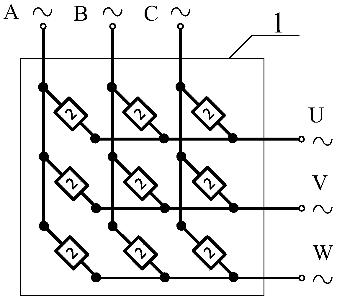
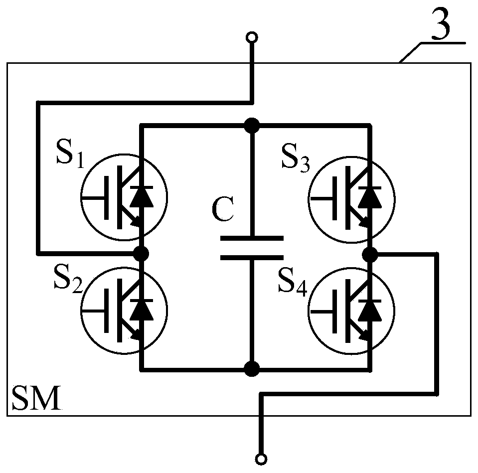
[0028] like figure 1 As shown, the modular multilevel matrix converter (M3C) system 1 specifically includes 9 bridge arms; each M3C bridge arm unit 2 includes N subunit modules, a bridge arm inductor L and a bridge arm short circuiter KB, like Figure 2a shown. Figure 2b The structure of the sub-module unit 3 is given, which specifically includes 4 power switch tubes IGBT (S1, S2, S3, S4) in an H-bridge structure, and a capacitor C.

[0029] image 3 A schematic diagram of the grouping of subunit modules on the bridge arm of the M3C system in the present invention is given, as image 3 As shown, it is an interleaved grouping: first, according to the input and output voltage conditions and the number of bridge arm sub-modules under normal operation, the minimum value of the capacitor voltage of the s...


PUM


Abstract

The invention discloses an M3C pre-charging method based on staggered grouping. According to the invention, on the premise that the capacitor voltage of an M3C system is charged, the pre-charging timeis shortened as much as possible and the control is simple, the pre-charging voltage can still reach a required set value when the input side (charging power supply) is relatively low and the numberof sub-module capacitors is relatively large and the voltage is relatively high, and meanwhile, the sub-module capacitor voltage is balanced. On the basis of the analysis, a grouping method is reformulated instead of simply dividing into two types, and an interleaved charging method is used at the same time, so that the charging time difference is reduced as much as possible, and the capacitor voltage is prevented from changing greatly after the charging is completed.

Description

technical field [0001] The invention relates to a sub-module capacitor precharging method of a modular multilevel matrix converter, and the specific method is suitable for any M3C topology converter. Background technique [0002] Modular multilevel matrix converter (M3C for short) is a new type of AC-AC power conversion device, which can realize arbitrary conversion of different amplitudes, frequencies, and power factors at the input and output terminals. The advantages of both matrix converter (MC) and modular multilevel converter (MMC) have great advantages in high-voltage and large-capacity power electronic conversion. In addition, M3C can also realize bidirectional conversion of power. Therefore, the M3C system has great prospects in future research and application. like figure 1 The topological structure of the M3C converter and its sub-modules is shown: the 3×3 M3C topology has 9 bridge arms, and each bridge arm is composed of a bridge arm inductor L and several ful...

Claims


Application Information

Patent Timeline
Patent Type & Authority Applications(China)
IPC IPC(8): H02M1/36H02M7/483
CPCH02M1/36H02M7/483H02M7/4835
Inventor 杭丽君王文杰何远彬卢浩沈磊陈圣伦
Owner HANGZHOU DIANZI UNIV
Learn More