Dust collector control device and dust collector

A technology for control devices and vacuum cleaners, applied in control systems, electronic reversing motor control, single motor speed/torque control, etc., can solve problems such as inaccurate adjustment of suction, complicated operation of vacuum cleaners, and inconvenient use

Inactive Publication Date: 2020-02-14
FORTIOR TECH SHENZHEN
4 Cites 1 Cited by

AI-Extracted Technical Summary

Problems solved by technology

Part of the suction is automatically adjusted by infrared detection of the amount of dust. However, the cost of infrared sensors is relatively high, which puts greater pressure on the cost of enterprises.
Another part of the vacuum cleaner adj...

Method used

For the problems referred to above, the Hallless brushless DC motor 40 runs smoothly and starts reliably, and what adopts is not to directly use the rotor Hall sensor, but needs the rotor position signal to control the motor changer in the operation of the brushless DC motor 40. Most phase and rotor position signal detection uses the detection of stator voltage, current, etc. to estimate the position of the rotor. In this solution, the brushless DC motor 40 does not have a Hall sensor in the vacuum cleaner control device, and the position and speed data of the rotor in the brushless DC motor 40 are all estimated by detecting the stator voltage, current, etc. The position of the rotor , so that the use of sensors in the brushless DC motor 40 control device is reduced, and the overall cost of the vacuum cleaner control device is reduced.
It should be noted that this program is controlled by the balance of microcontroller, load detection module and air volume detection module, so that the rotating speed of vacuum cleaner brushless DC motor 40 is in constant preset rotational speed range, that is, vacuum cleaner is subjected to Under the influence of the environment, the control vacuum cleaner has a stable suction.
The technical solution of the present invention detects the counter electromotive force of brushless DC motor 40 in real time by the load detection module in the vacuum cleaner control device, along with the variation of the counter electromotive force of brushless direct current motor 40, the...

Abstract

The invention discloses a dust collector control device and a dust collector. The dust collector control device comprises a microcontroller, a load detection module, an air volume detection module anda brushless DC motor. The input end of the load detection module is connected with the input end of the brushless DC motor. The output end of the load detection module and the output end of the air volume detection module are connected with the input end of the microcontroller. The output end of the microcontroller is connected with the input end of the brushless DC motor. The load detection module is used for detecting the counter electromotive force of the brushless DC motor in real time. The air volume detection module is used for collecting the suction force of the dust collector during working. The microcontroller controls the voltage output to the brushless DC motor according to the counter electromotive force of the brushless DC motor detected by the load detection module and the collected suction force of the dust collector during working, so as to control the rotating speed of the brushless DC motor to be constant in a preset rotating speed interval. The reliability of the dust collector is improved.

Application Domain

Single motor speed/torque control

Technology Topic

Mechanical engineeringVacuum cleaner +4

Image

  • Dust collector control device and dust collector
  • Dust collector control device and dust collector

Examples

  • Experimental program(1)

Example Embodiment

[0040] The technical solutions in the embodiments of the present invention will be clearly and completely described below with reference to the accompanying drawings in the embodiments of the present invention. Obviously, the described embodiments are only a part of the embodiments of the present invention, not all of the embodiments. Based on the embodiments of the present invention, all other embodiments obtained by those of ordinary skill in the art without creative efforts shall fall within the protection scope of the present invention.
[0041] It should be noted that if there are directional indications (such as up, down, left, right, front, back, etc.) involved in the embodiments of the present invention, the directional indications are only used to explain a certain posture (as shown in the accompanying drawings). If the specific posture changes, the directional indication also changes accordingly.
[0042] In addition, if there are descriptions involving "first", "second", etc. in the embodiments of the present invention, the descriptions of "first", "second", etc. are only used for the purpose of description, and should not be construed as indicating or implying Its relative importance or implicitly indicates the number of technical features indicated. Thus, a feature delimited with "first", "second" may expressly or implicitly include at least one of that feature. In addition, the technical solutions between the various embodiments can be combined with each other, but must be based on the realization by those of ordinary skill in the art. When the combination of technical solutions is contradictory or cannot be realized, it should be considered that the combination of such technical solutions does not exist. , is not within the scope of protection required by the present invention.
[0043] The invention provides a vacuum cleaner control device.
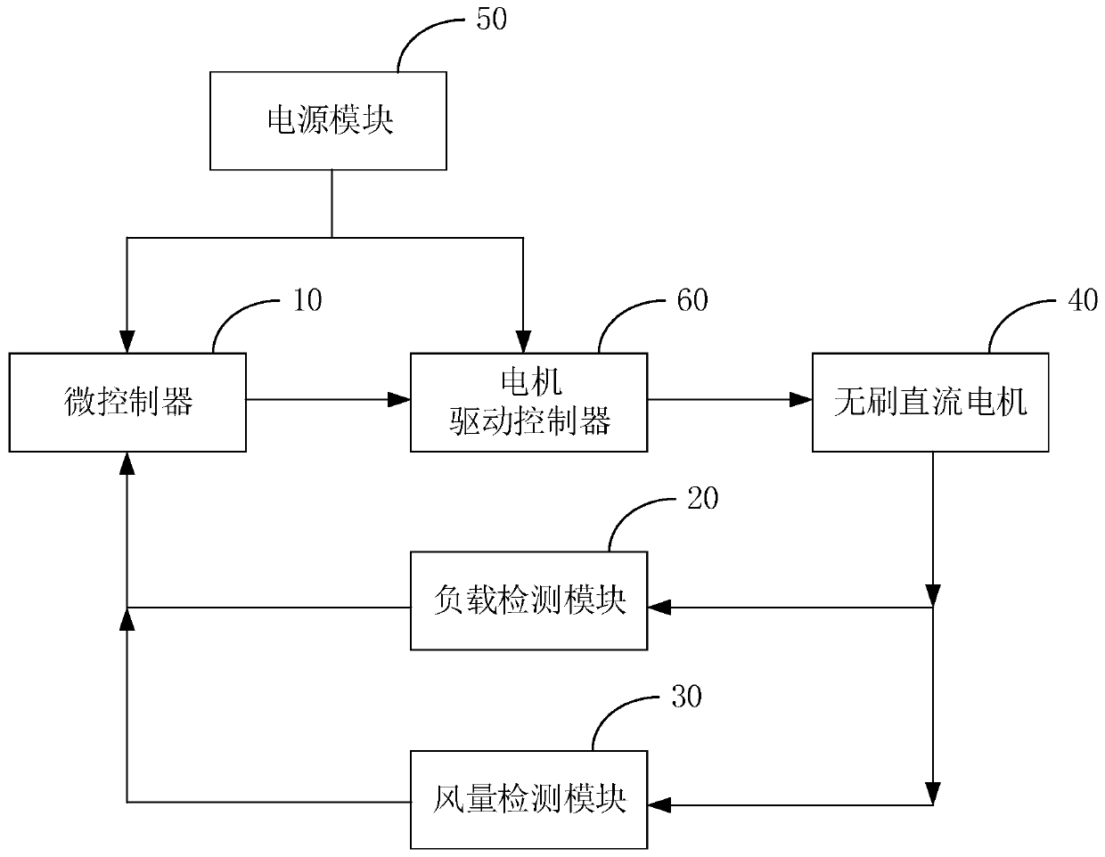
[0044] In an embodiment of the present invention, as figure 1 As shown, the vacuum cleaner control device includes a microcontroller 10, a load detection module 20, an air volume detection module 30 and a brushless DC motor 40;
[0045]The input end of the load detection module is connected to the input end of the brushless DC motor 40, the output end of the load detection module and the output end of the air volume detection module are respectively connected to the input end of the microcontroller, The output end of the microcontroller is connected to the input end of the brushless DC motor 40;
[0046] The load detection module is used to detect the back electromotive force of the brushless DC motor 40 in real time;
[0047] The microcontroller is used to control the voltage output to the brushless DC motor 40 according to the back electromotive force of the brushless DC motor 40 detected by the load detection module, so as to control the speed of the brushless DC motor 40 to be constant in the preset speed range;
[0048] The air volume detection module is used to collect the suction force of the vacuum cleaner when it is working;
[0049] The microcontroller is also used to control the voltage output to the brushless DC motor 40 according to the suction force of the vacuum cleaner during operation collected by the air volume detection module, so as to control the rotational speed of the brushless DC motor 40 to be constant at a preset value. Set the speed range.
[0050] In this solution, the brushless DC motor 40 is composed of a motor body and a driver, and is a typical mechatronic product. A brushless motor refers to a motor without brushes and commutators (or collector rings), also known as commutatorless motors. Therefore, the brushless DC motor 40 not only has the good speed regulation performance of the DC motor, but also has the simple structure, no commutation sparks, reliable operation and easy maintenance of the AC motor.
[0051] It should be noted that the brushless DC motor with Hall in the related art needs to be equipped with a relatively complex Hall sensor, which brings unfavorable factors to the reliability and manufacturing process of the motor. For example, the installation of the Hall sensor will increase the volume of the motor. If there are many signal transmission lines of the sensor, it is easy to cause interference to the motor. The working environment and temperature of the motor reduce the reliability of the Hall sensor. In addition, if the installation of the Hall sensor is not precise, it will cause problems with the running performance of the motor. .
[0052] In view of the above problems, the Hall-less brushless DC motor 40 runs smoothly and starts reliably, and the rotor Hall sensor is not used directly, but the rotor position signal is required to control the motor commutation during the operation of the brushless DC motor 40, and the rotor Most of the position signal detection uses is to detect the stator voltage, current, etc. to estimate the position of the rotor. In this solution, the brushless DC motor 40 does not have a Hall sensor in the vacuum cleaner control device, and the position and speed data of the rotor in the brushless DC motor 40 are estimated by detecting the stator voltage, current, etc. to estimate the position of the rotor , so that the use of sensors in the control device of the brushless DC motor 40 is reduced, and the overall cost of the control device of the vacuum cleaner is reduced.
[0053] In this solution, the load detection module performs real-time detection on the back electromotive force of the brushless DC motor 40 in the vacuum cleaner control device. It can be understood that the back EMF is that when the brushless DC motor 40 is started, the excitation winding establishes a magnetic field, the armature current generates another magnetic field, and the two magnetic fields interact, and the starter motor runs. The armature windings rotate in a magnetic field, thus creating a generator effect. In fact, the rotating armature generates an induced electromotive force, which is opposite to the polarity of the armature voltage. This self-induced electromotive force is called back electromotive force. In this solution, the back electromotive force is detected by the load detection module to output the back electromotive force signal to the microcontroller to calculate the real-time load of the brushless DC motor 40, and to control the output to no The voltage of the brushless DC motor 40 keeps the rotation speed of the brushless DC motor 40 constant within a preset rotation speed range. The solution realizes the stable operation of the vacuum cleaner controlled by the vacuum cleaner control device, and improves the reliability of the vacuum cleaner.
[0054] In this solution, the air volume detection module detects the suction force in real time when the vacuum cleaner is working. It can be understood that the air volume detection module may be an air pressure sensor, also called a differential pressure sensor, which is used to detect the suction force of the air outlet when the vacuum cleaner is working. Then, the voltage output to the brushless DC motor 40 is controlled by the microcontroller, so that the rotation speed of the brushless DC motor 40 is kept constant within a preset rotation speed range. Further, when the air volume detection module detects that the suction force of the vacuum cleaner is small, that is, when the rotational speed of the brushless DC motor 40 is less than the minimum value of the preset rotational speed interval, the microcontroller controls the rotational speed of the brushless DC motor 40 to increase. .
[0055] It should be noted that this solution uses the balance control of the microcontroller, the load detection module and the air volume detection module, so that the rotation speed of the brushless DC motor 40 of the vacuum cleaner is in a constant preset rotation speed range, that is, the vacuum cleaner is affected by the environment. , control the vacuum cleaner to have a stable suction.
[0056] The technical scheme of the present invention detects the back electromotive force of the brushless DC motor 40 in real time through the load detection module in the vacuum cleaner control device. The controller will control the voltage output to the brushless DC motor 40 according to the change of the load of the brushless DC motor 40 , so as to control the rotation speed of the brushless DC motor 40 to be constant within a preset rotation speed range. At the same time, the air volume detection module in the vacuum cleaner control device will also detect the suction force of the brushless DC motor 40 when it is working, and the microcontroller will control the voltage output to the brushless DC motor 40 according to the detected suction force to control the brushless DC motor. The speed of 40 is constant in the preset speed range. It can be understood that the state of the back electromotive force of the brushless DC motor 40 detected by the load detection module by the microcontroller to control the speed of the brushless DC motor 40 will affect the suction force detected by the air volume detection module. Therefore, in this solution, the load detection module, the air volume detection module and the microcontroller in the vacuum cleaner control device are used to control the rotational speed of the brushless DC motor 40 to be constant within a preset rotational speed range. It solves the problem that the vacuum cleaner cannot provide stable suction due to the deviation of suction due to different environments during the application of the vacuum cleaner. This solution improves the reliability of the vacuum cleaner.
[0057] In one embodiment, as figure 1 and figure 2 As shown, the vacuum cleaner control device also includes a power module 50 and a motor drive controller 60, the output end of the power module 50 is connected to the input end of the motor drive controller 60, and the output end of the motor drive controller 60 is connected The terminal is connected to the input terminal of the brushless DC motor 40;
[0058] The motor drive controller 60 is used to drive and control the operation of the one-way brushless stand-alone machine.
[0059] In this embodiment, the load detection module includes a back electromotive force collection circuit (not marked in the figure), the input end of the back electromotive force collection circuit is the input end of the load detection module, and the output end of the back electromotive force collection circuit is the the output terminal of the load detection module;
[0060] the back electromotive force collection circuit is used to collect the back electromotive force of the brushless DC motor 40, and output the back electromotive force signal to the microcontroller;
[0061] The microcontroller is further configured to calculate the real-time load of the brushless DC motor 40 according to the back electromotive force signal, so as to control the operation of the brushless DC motor 40 .
[0062] In one embodiment, the motor drive controller 60 includes a drive module 61 and an inverter bridge 62, and the vacuum cleaner control device further includes a current collection circuit (not marked in the figure) that collects the current of the brushless DC motor 40, The microcontroller, the driving module 61 , the inverter bridge 62 and the brushless DC motor 40 are connected in sequence, and the input end of the current acquisition circuit is connected to the input end of the brushless DC motor 40 , The output end of the current acquisition circuit is connected with the microcontroller;
[0063] the current acquisition circuit, used for acquiring the current of the brushless DC motor 40, and outputting a current signal to the microcontroller;
[0064] The microcontroller is further configured to calculate the rotational speed of the brushless DC motor 40 according to the back EMF signal, calculate the rotor position of the brushless DC motor 40 according to the current signal, and output a control signal to the Drive circuit;
[0065] the drive circuit, configured to output a drive signal to the inverter bridge 62 according to the control signal output by the microcontroller;
[0066] The inverter bridge 62 is configured to drive the brushless DC motor 40 to operate according to the driving signal output by the driving circuit.
[0067] Based on the above-mentioned embodiment, the technical effect achieved is: collecting the back electromotive force and current of the brushless DC motor 40 through the back electromotive force collection circuit, the current collection circuit, the microcontroller and the motor driver in the vacuum cleaner control device, and The rotational speed and rotor position of the brushless DC motor 40 are calculated to drive and control the operation of the brushless DC motor 40 . Further, since the Hall sensor is not used, the use of sensors in the control device of the brushless DC motor 40 is reduced, and the overall cost of the control device of the vacuum cleaner is reduced.
[0068] In one embodiment, the rotational speed of the brushless DC motor 40 includes:
[0069] According to the phase voltage equation of the brushless DC motor 40 The back-EMF flux linkage change rate dψ/dt of the brushless DC motor 40 is calculated, wherein di/dt is the current change rate determined according to the collected current, U is the driving voltage of the brushless DC motor 40, R is the stator resistance of the brushless DC motor 40 , L is the stator inductance of the brushless DC motor 40 , i is the current of the brushless DC motor 40 , and e is the back electromotive force of the brushless DC motor 40 ;
[0070] The rotor position of the brushless DC motor 40 is calculated according to the flux linkage change rate of the brushless DC motor 40 .
[0071] In this embodiment, calculating the rotor speed of the brushless DC motor 40 according to the collected current and back electromotive force of the brushless DC motor 40 includes:
[0072] Determine the rate of change di/dt of the current according to the collected current;
[0073] According to the current and the current change rate di/dt and the voltage equation of the brushless DC motor 40, the back EMF flux linkage change rate dψ/dt of the brushless DC motor 40 in the current rotation cycle is calculated, where U is the motor driving voltage, and R is the Stator resistance, L is the stator inductance, i is the collected current, and e is the back electromotive force of the brushless DC motor 40 in the current rotation cycle;
[0074] According to the back electromotive force of the brushless DC motor 40 in the previous rotation period, the two zero-crossing points of the back-EMF signal of the motor in the previous rotation period are determined, and the rotation angular velocity W of the brushless DC motor 40 is determined by calculating the time difference between the two zero-crossing points, and The rotational speed of the rotor of the brushless DC motor 40 is calculated according to the rotational angular velocity W of the brushless DC motor 40 .
[0075] In this embodiment, calculating the current position of the rotor of the brushless DC motor 40 according to the collected current and back electromotive force of the brushless DC motor 40 includes:
[0076] According to the collection times and collection rate of the current collection circuit of the brushless DC motor 40 in the current rotation cycle, determine the time T corresponding to the back-EMF flux linkage change rate dψ/dt in the current cycle;
[0077] The time T corresponding to the rotation angular velocity W, the back-EMF flux linkage rate of change dψ/dt and the back-EMF flux linkage rate of change dψ/dt in the current cycle is calculated by the equation y 0 =Asin(W 0 *t) and A=K*W 0 , calculate the value of the trigonometric function sin(W*T), where y 0 is the rate of change of back-EMF flux linkage, W 0 is the angular velocity, and A is caused by W 0 The back-EMF amplitude determined by the angular velocity, K is the back-EMF coefficient of the brushless DC motor 40;
[0078]According to the value of sin(W*T), the corresponding angle value is obtained by searching from the data table of preset angle values, so as to determine the current rotor position of the brushless DC motor 40 .
[0079] In one embodiment, the inverter bridge 62 is a bridge drive circuit composed of four switches. The rotor position information of the brushless DC motor 40 is provided for the vacuum cleaner control device without a position sensor, and the dependence of the control of the brushless DC motor 40 in the vacuum cleaner control device on the position sensor is solved.
[0080] In one embodiment, the air volume detection module is a wind pressure detection device. It can be understood that the wind pressure detection device is a wind pressure sensor, also called a differential pressure sensor, which is used to detect the size of the air volume of the air outlet when the vacuum cleaner is working, that is, the size of the suction force when the vacuum cleaner is working. In this way, the speed of the brushless DC motor 40 can be controlled by the detected suction force, so that the suction force of the vacuum cleaner can maintain a stable suction force.
[0081] In one embodiment, the rotational speed of the brushless DC motor 40 is less than or equal to 150,000 revolutions. It can be understood that the rotational speed value of the brushless DC motor 40 may be 5000 revolutions, 10000 revolutions, 150000 revolutions, etc., which is not limited here.
[0082] In addition, the present invention also provides a vacuum cleaner, which includes the above-mentioned vacuum cleaner control device; wherein, the vacuum cleaner control device includes a microcontroller, a load detection module, an air volume detection module, and a brushless DC motor 40;
[0083] The input end of the load detection module is connected to the input end of the brushless DC motor 40, the output end of the load detection module is connected to the first input end of the microcontroller, and the output end of the air volume detection module is connected to the second input end of the microcontroller, and the output end of the microcontroller is connected to the input end of the brushless DC motor 40;
[0084] The load detection module is used to detect the back electromotive force of the brushless DC motor 40 in real time;
[0085] The microcontroller is used to control the voltage input to the brushless DC motor 40 according to the back electromotive force of the brushless DC motor 40 detected by the load detection module, so as to control the speed of the brushless DC motor 40 to be constant in the preset speed range;
[0086] The air volume detection module is used to collect the suction force of the vacuum cleaner when it is working;
[0087] The microcontroller is also used to control the voltage output to the brushless DC motor 40 according to the suction force of the vacuum cleaner during operation collected by the air volume detection module, so as to control the rotational speed of the brushless DC motor 40 to be constant at a preset value. Set the speed range.
[0088] Since the vacuum cleaner adopts all the technical solutions of the above-mentioned embodiments, it has at least all the beneficial effects brought by the technical solutions of the above-mentioned embodiments, which will not be repeated here.
[0089] The above descriptions are only optional embodiments of the present invention, and are not intended to limit the scope of the present invention. Under the inventive concept of the present invention, any equivalent structural transformations made by using the contents of the description and drawings of the present invention, or direct/indirect Applications in other related technical fields are included in the scope of patent protection of the present invention.

PUM

no PUM

Description & Claims & Application Information

We can also present the details of the Description, Claims and Application information to help users get a comprehensive understanding of the technical details of the patent, such as background art, summary of invention, brief description of drawings, description of embodiments, and other original content. On the other hand, users can also determine the specific scope of protection of the technology through the list of claims; as well as understand the changes in the life cycle of the technology with the presentation of the patent timeline. Login to view more.
Why Eureka
Try Eureka