
Lens module, control method and electronic equipment

The technology of a lens module and a control method is applied to televisions, electrical components, color TVs, etc., and can solve problems such as thickening of mobile terminal bodies, increasing the total length of lens modules, and increasing the focal length of optical lenses, etc., so as to reduce the Small thickness, small overall lens length, and easy storage

Active Publication Date: 2020-02-14
GUANGDONG OPPO MOBILE TELECOMM CORP LTD
View PDF3 Cites 7 Cited by
  • Summary
  • Abstract
  • Description
  • Claims
  • Application Information

AI Technical Summary

Problems solved by technology

[0002] As the resolution of the image sensor increases, the size of the image sensor will become larger, that is, the image height of the image will become larger. When the field of view remains unchanged, the focal length of the optical lens will also become larger. The corresponding lens size The total length of the group also increases
However, the increase in the total length of the lens module will lead to a thicker body of the mobile terminal, which is not conducive to the thinning of the mobile terminal.

Method used


Image

  • Lens module, control method and electronic equipment
  • Lens module, control method and electronic equipment
  • Lens module, control method and electronic equipment

Examples


Embodiment Construction

[0020] The embodiments of the present application are described in detail below. Examples of the embodiments are shown in the accompanying drawings, wherein the same or similar reference numerals indicate the same or similar elements or elements with the same or similar functions. The embodiments described below with reference to the accompanying drawings are exemplary, and are intended to explain the present application, but should not be understood as a limitation to the present application.

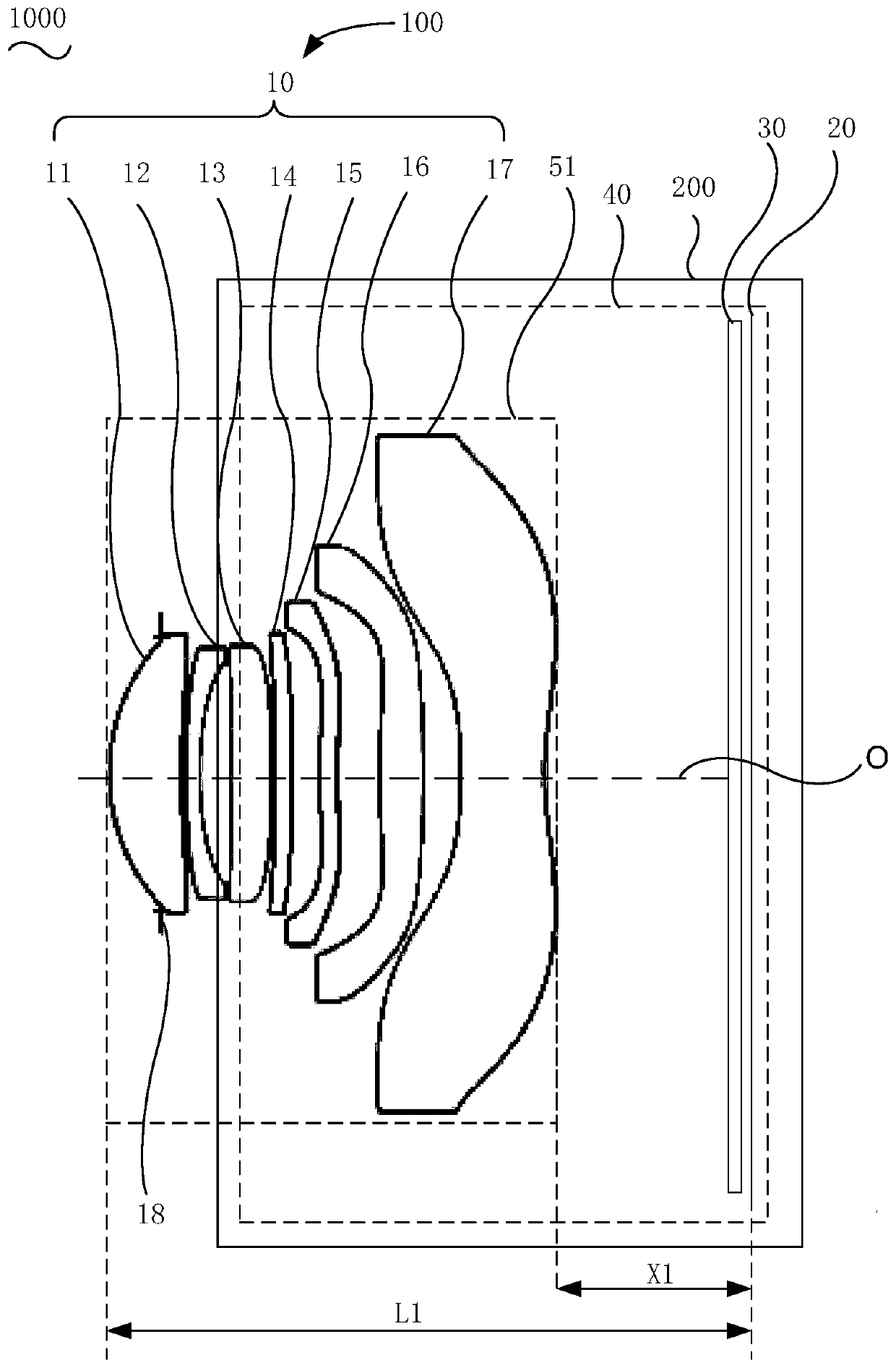
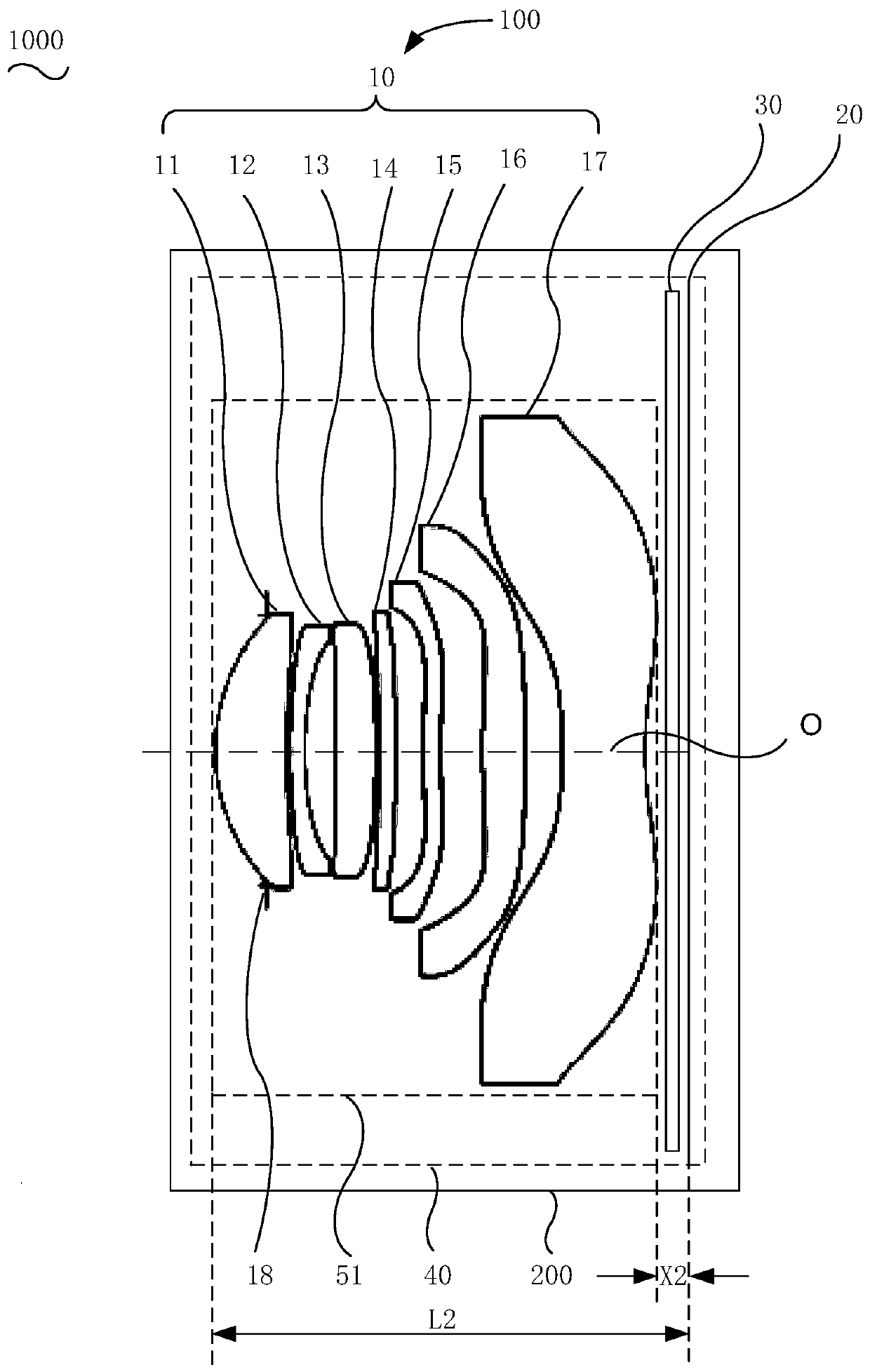
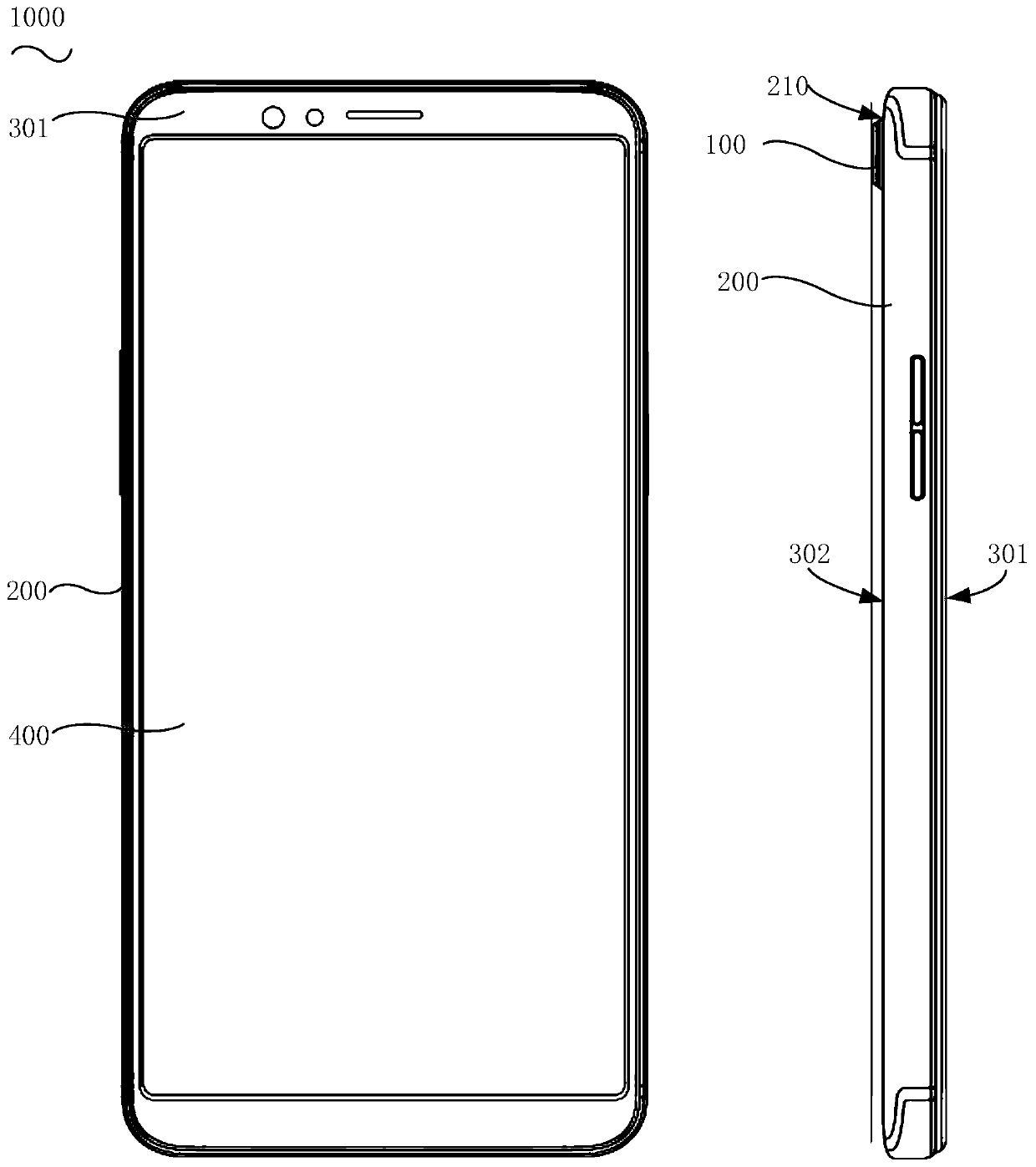
[0021] Please refer to figure 1 with figure 2 The lens module 100 of the embodiment of the present application includes an optical lens 10 and a photosensitive element 20. In the direction from the object side to the image side of the lens module 100, the optical lens 10 and the photosensitive element 20 are arranged in sequence, and the optical lens 10 can be arranged along the lens The optical axis O of the module 100 moves, and the position of the photosensitive element 20 on the optic...


PUM


Abstract

The invention discloses a lens module, a control method and electronic equipment. The lens module comprises an optical lens and a photosensitive element, the optical lens and the photosensitive element are sequentially arranged in the direction from the object side to the image side of a lens module, and the position of the photosensitive element on the optical axis is relatively fixed. When the lens module is switched from the non-working state to the working state, the optical lens moves towards the object side of the lens module along the optical axis; when the lens module is switched fromthe working state to the non-working state, the optical lens moves towards the image side of the lens module along the optical axis. The optical lens moves towards the object side direction or the image side direction of the lens module along the optical axis. According to the lens module, switching between the working state and the non-working state of the lens module is achieved, when the lens module is in the non-working state, the total length of the lens of the lens module is small, the lens module can be conveniently contained in electronic equipment, and therefore the thickness of the electronic equipment can be reduced.

Description

Technical field [0001] This application relates to the field of imaging technology, and in particular to a lens module, a control method and electronic equipment. Background technique [0002] With the increase of the resolution of the image sensor, the size of the image sensor will become larger, that is, the image height of the image will become larger, and the focal length of the optical lens will also become larger when the field of view remains unchanged. The total length of the group also increases accordingly. The increase in the total length of the lens module will cause the body of the mobile terminal to become thicker, which is not conducive to the thinning of the mobile terminal. Summary of the invention [0003] The embodiments of the present application provide an optical lens, an optical lens control method, a camera module, and electronic equipment. [0004] The lens module of the embodiment of the present application includes an optical lens and a photosensitive el...

Claims


Application Information

Patent Timeline
Patent Type & Authority Applications(China)
IPC IPC(8): H04N5/225H04N5/232
CPCH04N23/57H04N23/55H04N23/667
Inventor 杨鑫
Owner GUANGDONG OPPO MOBILE TELECOMM CORP LTD
Learn More