
Image sensor reading circuit and reading method for suppressing sunspot effect

An image sensor and readout circuit technology, applied in image communication, television, electrical components, etc., can solve the problems of CDS error, clamping voltage deviation, affecting image quality, etc., to achieve the effect of image quality assurance

Pending Publication Date: 2020-02-14
CHENGDU LIGHT COLLECTOR TECH
View PDF6 Cites 2 Cited by
  • Summary
  • Abstract
  • Description
  • Claims
  • Application Information

AI Technical Summary

Problems solved by technology

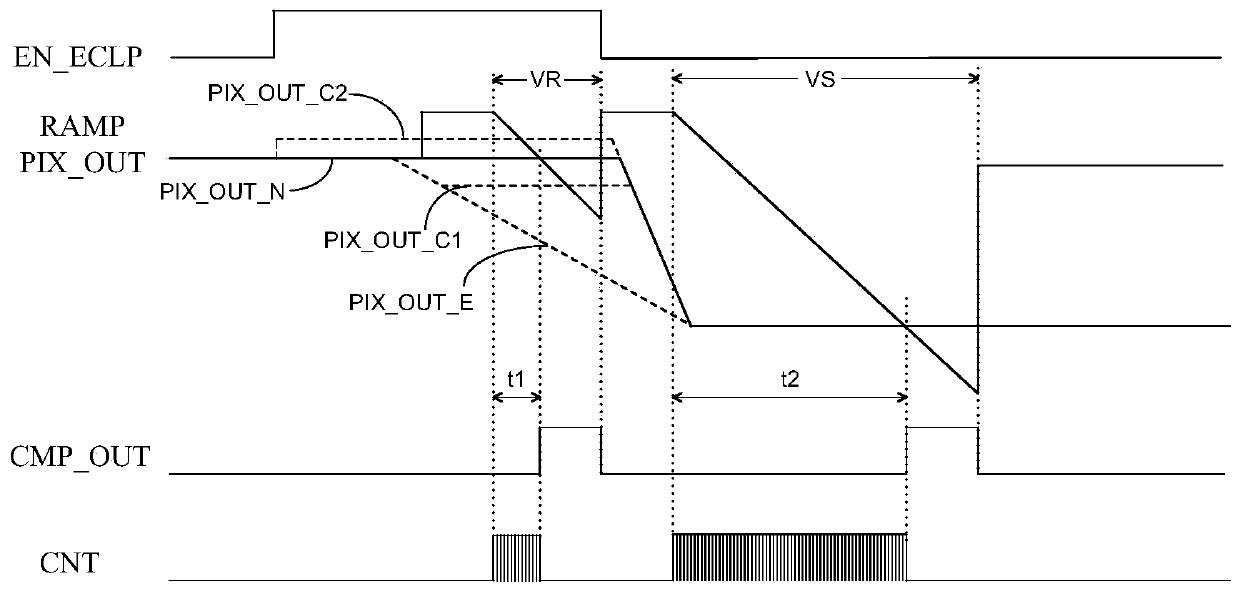
The function of the clamping circuit is to make the actual pixel unit output terminal PIX_OUT in the vicinity of PIX_OUT_N in the VR stage, but because the threshold voltage Vth1 of the transistor M1 will be affected by factors such as process and temperature, the clamping voltage will deviate. Low voltage, PIX_OUT is image 3 Medium PIX_OUT_C1, D1 is still too large, can not achieve the effect of eliminating the sunspot effect
If the clamping voltage is too high, PIX_OUT is image 3 In PIX_OUT_C2, D1 will be too small, and ΔD will be too large. The influence of the sunspot effect of this pixel unit can be eliminated, but the clamping circuit is enabled during the exposure voltage readout process of each pixel unit, that is, all readout circuits The clamping circuit is enabled at the same time, so this makes the output of other normal pixel units also larger, resulting in errors in the CDS of these normal pixel units, affecting image quality

Method used


Image

  • Image sensor reading circuit and reading method for suppressing sunspot effect
  • Image sensor reading circuit and reading method for suppressing sunspot effect
  • Image sensor reading circuit and reading method for suppressing sunspot effect

Examples


Embodiment Construction

[0027] In order to make the purpose, technical solution and advantages of the present invention clearer, the specific implementation manners of the present invention will be further described in detail below in conjunction with the accompanying drawings.

[0028] as attached figure 2As shown, the present invention provides an image sensor readout circuit that suppresses the sunspot effect, and the readout circuit is obtained by improving a conventional ADC circuit. The specific readout circuit includes a detection unit DET, a comparator CMP and a counter CNT, wherein the detection unit DET includes two input terminals, an enable control terminal and an output terminal, wherein the two input terminals of the detection unit are respectively connected to the pixel The unit output terminal PIX_OUT and the reference voltage VR_ECLP_A, the enable control terminal of the detection unit is connected to the enable signal EN_ECLP, wherein the enable signal EN_ECLP controls whether the ...


PUM


Abstract

The invention discloses an image sensor reading circuit for suppressing a sunspot effect. The circuit comprises a detection unit, a comparator and a counter. The detection unit comprises two input ends, an enabling control end and an output end; wherein two input ends of the detection unit are respectively connected with an output end of a pixel unit and a reference voltage; the enabling control end of the detection unit is connected with an enable signal; wherein the output end of the detection unit is connected with the input end of the counter, one end of the comparator is connected with the output end of the pixel unit, the other end of the comparator is connected with an oblique wave signal, the output end of the comparator is connected with the input end of the counter, and the output end of the counter outputs the exposure digital quantity of the pixel unit. The image sensor reading circuit capable of suppressing the sunspot effect can ensure that abnormal black spots do not appear on an image when the sunspot effect occurs due to strong light irradiation, and does not influence the image quality.

Description

technical field [0001] The invention relates to the field of image sensor readout circuits, in particular to an image sensor readout circuit and a readout method for suppressing the sunspot effect. Background technique [0002] Under strong light, the photodiode of the pixel unit in the CIS (CMOS image sensor) will generate redundant photoelectrons, and these photoelectrons will accumulate in the floating node FD of the pixel unit, which will greatly reduce the reset voltage of the pixel unit, which in turn will lead to the correlation in the subsequent readout circuit. Double sampling (CDS) fails, the reset voltage value corresponding to these pixel units is smaller than the actual value, and black spots will appear on the CIS image, which is the sunspot effect. In order to avoid this situation, a pixel output clamping circuit is added to the traditional CIS design. During the reset voltage readout phase, the clamping circuit can keep the pixel output at a not too low volta...

Claims


Application Information

Patent Timeline
IPC IPC(8): H04N5/378H04N5/359
CPCH04N25/62H04N25/75
Inventor 蔡化高菊陈飞苪松鹏陈正
Owner CHENGDU LIGHT COLLECTOR TECH
Learn More