Concrete processing equipment

A technology for processing equipment and concrete, which is applied in the direction of clay preparation device, mixing operation control, mixing operation control device, etc. It can solve the problems of poor mixing uniformity, lower production efficiency and production benefits, and long mixing time, so as to achieve uniform mixing, The effect of improving the stirring effect and reducing the stirring time

Inactive Publication Date: 2020-02-18
衡东盛世商品混凝土有限公司
View PDF5 Cites 1 Cited by
  • Summary
  • Abstract
  • Description
  • Claims
  • Application Information

AI Technical Summary

Problems solved by technology

[0002] Driven concrete production equipment is to input various raw materials in large quantities at one time, and then turn on the mixing mechanism. Not only the mixing uniformity of each raw material is poor, but also the mixing time required to reach the mixing standard is long, which reduces production efficiency and production benefits.

Method used


Image

  • Concrete processing equipment
  • Concrete processing equipment
  • Concrete processing equipment

Examples


Embodiment 1

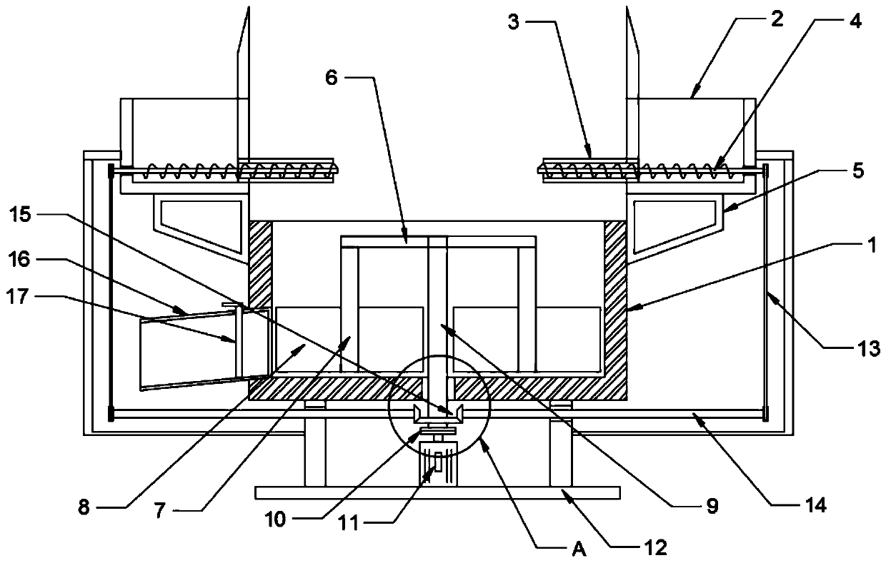
[0022] see Figure 1-4 , in an embodiment of the present invention, a concrete processing equipment includes a mixing tank 1 and a mixing plate 8; A plurality of raw material boxes 2 distributed in a circle, the raw material boxes 2 are detachably connected with the upper edge of the mixing tank 1 through the mounting frame 5, which is convenient for increasing and decreasing the quantity of the raw material boxes 2, and the inner side of the raw material box 2 is connected with the feeding pipe 3, the feeding pipe 3 Extending to the top of the mixing tank 1, the feeding pipe 3 is provided with a screw feed roller 4, and the screw feed roller 4 extends into the raw material box 4; specifically, each raw material of the concrete is placed in the circular distribution according to the required amount. In the raw material box 2, the screw feed roller 3 feeds each raw material at a constant speed and quantitatively, and the stirring structure performs agitation and processing of e...

Embodiment 2

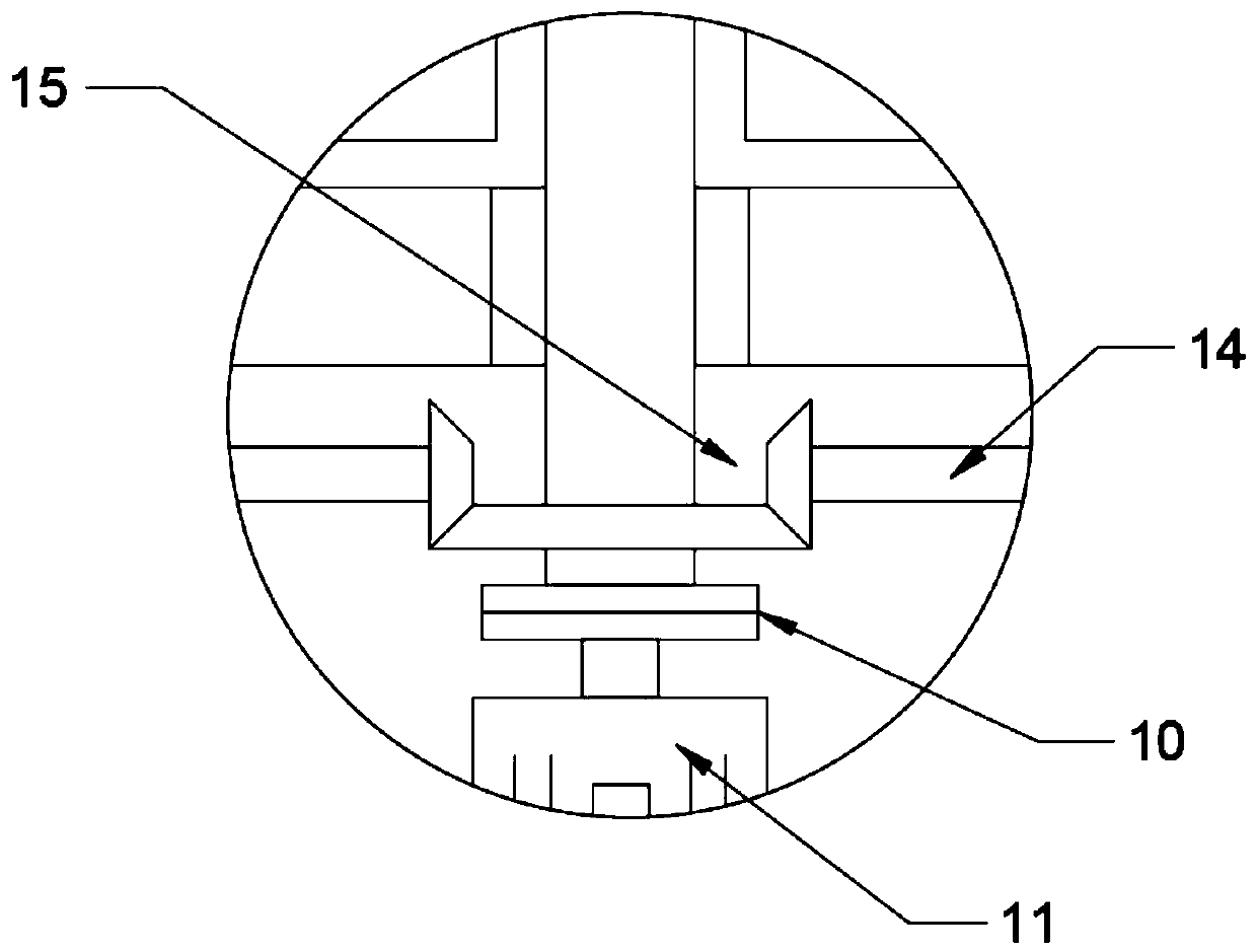
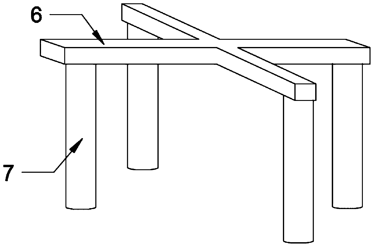
[0024] The difference between this embodiment and Embodiment 1 is that the stirring mechanism includes a turret 6, the turret 6 is cross-shaped, the outer end of the turret 6 is fixedly connected with a suspension shaft 7, and the suspension shaft 7 is fixedly connected with a stirring plate 8, The stirring range is covered comprehensively, and the stirring effect is ensured; the central position of the turret 6 is fixedly connected with the stirring shaft 9, and the stirring shaft 9 extends to the bottom of the stirring tank 1 and is connected with the output shaft of the stirring motor 11 through the coupling 10, thereby driving The stirring plate 8 rotates to realize stirring.

[0025] In order to realize the rotary feeding of the screw feed roller 3, the end of the screw feed roller 3 is connected with a transmission shaft 14 through a transmission belt 13, and the transmission shaft 14 is connected with a stirring shaft through a transmission gear set 15, and the transmiss...


PUM


Abstract

The invention discloses concrete processing equipment which comprises a stirring tank, a stirring plate and a stirring mechanism. A plurality of raw material boxes distributed in circumference are arranged above the stirring tank, feeding tubes communicate to the inner sides of the raw material boxes, and spiral feeding rollers are arranged in the feeding tubes. By arranging the raw material boxesdistributed in circumference and communicating to the feeding tubes, raw materials are quantatively and synchronously fed, so that the raw materials are uniformly stirred subsequently, the stirring effect is improved and the stirring time is shortened. By arranging the stirring plate connected to a suspension shaft through a rotating rack, the stirring range of the stirring plate is ensured. By arranging the spiral feeding rollers connected to the stirring shaft through a transmission mechanism, feeding and stirring are synchronized, so that a driving structure and a control node are simplified.

Description

technical field [0001] The invention relates to the field of concrete processing equipment, in particular to concrete processing equipment. Background technique [0002] Driven concrete production equipment is to input various raw materials in large quantities at one time, and then turn on the mixing mechanism. Not only the mixing uniformity of each raw material is poor, but also the mixing time required to reach the mixing standard is long, which reduces production efficiency and production benefits. . [0003] The application provides a concrete processing equipment. Contents of the invention [0004] The object of the present invention is to provide a concrete processing equipment to solve the problems raised in the background art above. [0005] To achieve the above object, the present invention provides the following technical solutions: [0006] A concrete processing equipment, comprising a mixing tank, a mixing plate and a mixing mechanism; a plurality of raw mat...

Claims


Application Information

Patent Timeline
IPC IPC(8): B28C5/16B28C5/08B28C7/00B28C7/10
CPCB28C5/0831B28C5/0868B28C5/16B28C7/0053B28C7/10
Inventor 宾霞胡园园朱玉圆
Owner 衡东盛世商品混凝土有限公司
Why Eureka
Try Eureka