Method and device for determining occupied position of train

A technology for occupying positions and trains, which is applied in the field of determining the occupied positions of trains, and can solve problems affecting train operation efficiency and the inability to extend the movement authorization of rear vehicles, so as to achieve the effects of improving train operation capacity, train operation efficiency, and accuracy

Active Publication Date: 2020-02-18
通号城市轨道交通技术有限公司
6 Cites 12 Cited by

AI-Extracted Technical Summary

Problems solved by technology

[0004] In the prior art, the axle counting section in the occupied state reported by the CI or the adjacent idle state axle counting section before and after the axle counting section may be misjudged as the occup...

Method used

In implementation, current train is non-communication train, and train continues to move forward, rolls out above-mentioned target axle counting section, when occupying two axle counting sections, at first, can determine the shortest car length of current train, The overhang length of the current train, the maximum operating speed of the current train, and the braking acceleration of the current train. Then, the maximum running distance of the head of the current train can be calculated based on the shortest train length of the aforementioned current train, the overhang length of the current train, the highest running speed of the current train, and the braking acceleration of the current train, and the corresponding calculation formula can be Ldis =Ltrain-Lxc+Vmax×Tstde, among them, Ldis represents the maximum running distance of the head, Ltrain represents the shortest train length of the current train, Lxc represents the overhang length of the current train, Vmax represents the maximum running speed of the current train, Tstde represents the axle counting system and the target The delay of the controller is Tstde. Afterwards, the preset maximum retreat distance of the current train can be obtained, and based on the aforementioned shortest train length, the aforementioned overhang length and the aforementioned maximum retreat distance, the maximum running distance of the tail of the current train can be determined. The corresponding formula can be Ldis tail=Ltrain-Lxc +L retreat, wherein, Ldis tail represents the maximum running distance of the tail, Ltrain represents the shortest train length of th...

Abstract

The embodiment of the invention discloses a method and device for determining the occupied position of a train. A target controller is constructed based on CI and QC. The method for determining the occupied position of the train includes the steps that the target controller collects position information of the current train and determines the maximum travel distance of the head of the current train and the maximum travel distance of the tail of the current train; and the target controller determines the occupied position of the current train based on the position information, the maximum travel distance of the head and the maximum travel distance of the tail. By means of the method and device, the train operation efficiency and the train operation capacity are effectively improved, the resource consumption can be reduced, communication delay between the QC and the CI is reduced, the accuracy of the determined train occupied position can be effectively improved, the train operation efficiency is further improved, and the train operation capacity is improved.

Application Domain

Technology Topic

Image

  • Method and device for determining occupied position of train
  • Method and device for determining occupied position of train
  • Method and device for determining occupied position of train

Examples

  • Experimental program(1)

Example Embodiment

[0056] The specific embodiments of the present invention will be further described below with reference to the accompanying drawings. The following examples are only used to illustrate the technical solutions of the present invention more clearly, and cannot be used to limit the protection scope of the present invention.
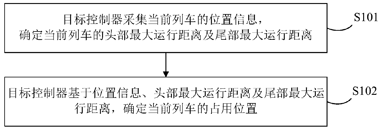
[0057] figure 1 A schematic flowchart of a method for determining an occupied position of a train provided by this embodiment is shown, including:
[0058] S101, the target controller collects the position information of the current train, and determines the maximum running distance of the head and the maximum running distance of the tail of the current train.
[0059] Wherein, the target controller refers to a new type of zone controller constructed based on CI and ZC, for example, ZC and CI can be merged to construct a target controller.
[0060] The maximum running distance of the head refers to the maximum distance that the current train may run forward (ie, the running direction of the train).
[0061] The maximum running distance at the rear refers to the maximum distance that the current train may run backwards.
[0062] In implementation, when the occupied position of a certain train (which may be called the current train) needs to be determined, first, the target controller can collect the position information of the current train, that is, the position information when the current train communicates normally. Then, the target controller may determine the aforementioned maximum running distance of the head of the current train, and may determine the aforementioned maximum running distance of the tail of the current train.
[0063] S102, the target controller determines the occupied position of the current train based on the position information, the maximum running distance of the head and the maximum running distance of the tail.
[0064] In the implementation, the target controller obtains the position information of the current train again, and determines the maximum running distance of the head of the current train and the maximum running distance of the tail of the current train. The target controller may calculate the envelope range of the position of the current train based on the position information of the current train, the maximum running distance of the head and the maximum running distance of the tail of the current train, and determine the occupied position of the current train based on the envelope range.
[0065] It can be seen from the above technical solutions that in the embodiment of the present invention, a target controller is constructed based on ZC and CI, and the target controller can determine the occupancy of the current train based on the position information of the train, the maximum running distance of the head, and the maximum running distance of the tail. Location. In this way, on the one hand, the occupied position of the current train is determined based on the position information of the train, the maximum running distance of the head and the maximum running distance of the tail, so as to avoid the misjudgment of the axle counting section as the occupied state, thereby effectively improving the The accuracy of the determined train occupancy position can effectively improve train operation efficiency and train operation capability; on the other hand, building a target controller based on the integration of ZC and CI can also simplify system structure, interface, and reduce resources. consumption, and reduce the communication delay between ZC and CI, so that the accuracy of the determined train occupancy position can be effectively improved, thereby further improving the train operation efficiency and improving the train operation capacity.
[0066] Further, on the basis of the above method embodiments, when the current train is downgraded from a communication train to a non-communication train, the position information of the current train can be determined based on the latest position report information, and the position information of the current train can be determined based on the maximum running speed of the train, the target controller and the target controller. Based on the communication delay and braking acceleration between the current trains, the maximum running distance of the head is determined, and the maximum running distance of the tail is determined based on the occupied/idle status of the axle counting section and the communication delay between the target controller and the axle counting system. Correspondingly, the processing of the above step S101 may be as follows: the target controller collects the latest position report information before the current train is downgraded, and determines the position information of the current train from the latest position report information; The communication delay between the controller and the current train and the braking acceleration of the current train; based on the maximum running speed, the communication delay between the target controller and the current train, and the braking acceleration, determine the maximum running distance of the head of the current train; get The preset maximum retreat distance corresponding to the current train is determined as the maximum running distance of the tail of the current train.
[0067] Wherein, the preset maximum retreat distance refers to a preset maximum distance that the train may retreat, such as may be determined according to historical operating conditions.
[0068] In the implementation, considering that the train is usually a communication train when it is running normally, and is degraded to a non-communication train when braking, the position information before demotion can be determined as the position information when the current train is braking. Specifically, when the current train is a communication train, the target controller can acquire the position report information of the communication train in real time, and can determine the latest position report information of the communication train. Then, when the communication train performs emergency braking, the communication train will be downgraded to a non-communication train, so the target controller can obtain the latest position report information of the current train, and can determine the position information of the current train from the latest position report information. After that, the target controller can first determine the maximum running speed of the current train, and determine the communication delay between the target controller itself and the current train, and the braking acceleration of the current train. Then, the target controller may calculate the maximum running distance of the head of the current train based on the aforementioned maximum running speed, the aforementioned communication delay between the aforementioned target controller and the train, and the aforementioned braking acceleration of the current train. At the same time, the target controller can also obtain the preset maximum retreat distance corresponding to the current train, and determine the preset maximum retreat distance as the maximum running distance of the rear of the current train. In this way, the determined position information of the current train can be made more accurate, thereby further improving the operating efficiency of the train and improving the operating capability of the train.
[0069] Wherein, the formula for determining the maximum running distance of the head of the current train may be as follows:
[0070]
[0071] where the L dis represents the maximum possible position of the head of the current train, the V max represents the maximum running speed of the current train, the T zc-vobc represents the communication delay between the target controller and the current train, the a eb Indicates the braking acceleration of the current train.
[0072] It can be understood that when the current train is a communication train (that is, a position reporting train), there is a communication delay between the VOBC (Vehicle On-Board Controller, on-board controller) and the target controller. Therefore, refer to figure 2 , the position information of the current train can be used to take the maximum running distance of the head during the maximum communication delay time, and the maximum running distance of the tail generated when the train retreats under the most unfavorable situation as the envelope range of the occupied position of the current train.
[0073] It should be noted that before the current train is downgraded, see image 3 , the target controller stores the position information of the current train, and the distance from the emergency braking of the current train to the stop of the train is When the target controller considers the train to be downgraded, the preset maximum retreat distance of the train under the most unfavorable situation is considered backward as the maximum running distance at the rear, and the forward L dis The distance is used as the maximum running distance of the head of the train. Based on the maximum running distance of the head and the maximum running distance of the tail, both are used as the envelope range of the occupied position of the current train. Among them, the leftmost end of the maximum running distance of the tail is the possible position of the tail of the current train, and the rightmost end of the maximum running distance of the head is the possible position of the head of the current train.
[0074] Further, on the basis of the above method embodiments, when the current train is a non-communication train and occupies an axle counting section after completing the braking, the occupied position of the current train may also be determined, and the corresponding processing of the above step S101 may be as follows: The target controller determines the target axle counting section occupied by the current train, and determines the target axle counting section as the position information of the current train; determines the end point of the target axle counting section, and determines the maximum running distance of the head of the current train based on the end point; The starting point of the target axle counting section is determined, and the preset maximum retreat distance corresponding to the current train is obtained; based on the starting point and the preset maximum retreat distance corresponding to the current train, the maximum running distance of the tail of the current train is determined.
[0075] In implementation, since the target controller cannot determine the state of the non-communication train after the current train brakes and stops, it may continue to move forward/backward or remain stationary, so it is necessary to rely on the occupancy state of the axle counting system to determine the state of the non-communication train. possible operating range. Specifically, as Figure 4 As shown, when the axle counting section (that is, the target axle counting section) W2 where the non-communication vehicle is located is in the occupied state, and the adjacent axle counting sections W1 and W3 are both in the idle state, the target axle counting section W2 can be determined. is the position information of the current train, that is, the current train is within the target axle counting section. Then, the end point of W2 (that is, the right end point of W2) can be determined, and based on the end point, the running distance of the train within the maximum delay time of the target axle counting section (that is, the maximum running distance of the head) can be determined forward (that is, to the right) , the calculation formula of this distance can be V max ×T stde , where V max Indicates the current maximum running speed of the train. Then, the starting point of W2 (ie, the left end point of W2) can be determined, and the preset maximum retreat distance corresponding to the current train can be obtained, and the maximum running distance of the rear of the current train can be determined based on the aforementioned starting point and the preset maximum retreat distance. Similarly, the aforementioned maximum running distance of the head and the maximum running distance of the tail can be used as the envelope range of the occupied position of the current train. In this way, the accuracy of the determined occupied position of the current train can be further improved, thereby further improving the operating efficiency and operation capability of the train.
[0076] Further, on the basis of the above method embodiment, when the current train is a non-communication train and occupies two axle counting sections in sequence, the maximum running distance of the head and the maximum running distance of the tail of the current train can also be calculated, and the corresponding above steps Part of the processing of S101 may be as follows: determine the shortest train length of the current train, the hanging length of the current train, the maximum running speed of the current train and the braking acceleration of the current train; The dynamic acceleration is used to determine the maximum running distance of the head of the current train; the preset maximum retreat distance of the current train is obtained, and the maximum running distance of the rear of the current train is determined based on the shortest vehicle length, overhang length and maximum retreat distance.
[0077] In implementation, when the current train is a non-communication train, and the train continues to run forward, when it leaves the target axle counting section and occupies two axle counting sections, first, the shortest train length of the current train and the Overhang length, maximum running speed of the current train, and braking acceleration of the current train. Then, based on the shortest train length of the current train, the hanging length of the current train, the maximum running speed of the current train, and the braking acceleration of the current train, the maximum running distance of the head of the current train can be calculated, and the corresponding calculation formula can be Ldis =L train -L xc +V max ×T stde , where L dis Indicates the maximum running distance of the head, L train Indicates the shortest length of the current train, L xc Indicates the current train overhang length, V max Indicates the maximum running speed of the current train, T stde It means that the delay between the axle counting system and the target controller is T stde. After that, the preset maximum retreat distance of the current train can be obtained, and based on the aforementioned shortest vehicle length, the aforementioned overhang length and the aforementioned maximum retreat distance, the maximum running distance of the rear of the current train can be determined, and the corresponding formula can be L dis尾 =L train -L xc +L 退行 , where L dis尾 Indicates the maximum running distance of the tail, L train Indicates the shortest length of the current train, L xc Indicates the overhang length of the current train, L 退行 Indicates the preset maximum retreat distance of the current train. In this way, the maximum running distance of the head/tail of the current train is determined based on the shortest vehicle length, the hanging length, the maximum running speed, the braking acceleration and the maximum retreat distance, which can further improve the accuracy of the determined occupied position of the current train, thereby further Improve train operation efficiency and operational capacity.
[0078] Specifically, as Figure 5 and Image 6 As shown, W2 can be defined as driving out of the axle counting section, and W3 can be defined as driving in the axle counting section. For entering the axle counting section W3, consider that the last wheelset of the train has just left the axle counting section W2. Due to the communication delay between the axle counting system and the target controller, the target controller still receives the occupied state. The possible running range of the front (ie the maximum running distance of the head) is L dis =L train -L xc +V max ×T stde , for driving out of the axle counting section W2, consider that the first wheel pair of the current train has just entered the axle counting section W3. At this time, the train retreats. Due to the communication delay between the axle counting system and the target controller, the target controller still receives Occupied state, so the possible backward running range of the non-communication vehicle (that is, the maximum running distance at the rear) is L dis =L train -L xc +L 退行.
[0079] Further, on the basis of the above method embodiments, when the current train occupies one axle counting section during operation, part of the processing in the above step S101 may be as follows: determine the exit axle counting section when the current train occupies two axle counting sections. section and entering the axle counting section, and determine the minimum interval time from when the last wheel set of the current train exits and exits the axle counting section until the first wheel pair of the current train leaves the entering axle counting section; when the target When the controller receives the idle message of driving out of the axle counting section, it determines that the current train will not leave and enter the axle counting section within the minimum interval time; The maximum running distance of the head; the preset maximum retreat distance and overhang length of the current train are obtained, and the maximum running distance of the rear of the current train is determined based on the preset maximum retreat distance and overhang length.
[0080] The preset minimum interval duration refers to the shortest duration of the train running in an axle counting section, that is, when the running duration is less than the duration, the train is still in the current axle counting section.
[0081] In the implementation, the current train is a non-communication train and continues to run until it just exits the above-mentioned exit axle counting section W2, that is, when only one axle counting section is occupied, the interval from the current time to the receipt of the W2 idle message may be based on The duration determines the maximum running distance of the head of the current train. Specifically, first of all, the exiting and entering axle counting sections when the current train occupies the two axle counting sections W2 and W3 can be determined, and it can be determined that the current train has completely left the above-mentioned exiting axle counting sections. The minimum interval time until the first wheel pair of the current train leaves the above-mentioned entering axle counting section. Then, when the target controller receives the above-mentioned idle message for exiting the axle counting section, it can determine that the current train will not leave the preceding entering axle counting section within the aforesaid minimum interval duration, that is, within the aforementioned interval duration, the current train All trains will enter the axle counting section as described above. Then, the target controller may determine the length of the aforesaid entering axle counting section as the maximum running distance of the head of the current train. Afterwards, the target controller may acquire the preset maximum retreat distance and the overhang length of the current train, and may determine the sum of the preset maximum retreat distance and the overhang length as the maximum retreat distance of the tail. In this way, the maximum running distance of the head of the current train is determined based on the minimum interval time, which can further improve the accuracy of the position occupied by the train, and improve the operating efficiency and operation capability of the train.
[0082] see Figure 7 , when the target controller receives that the entry into the axle counting section is in the occupied state and the exiting axle counting section is in the idle state, it can be determined that the last wheelset of the non-communication train (ie the current train) has just left the axle counting section W2 The interval time until the first wheelset just exits the axle counting section W3 is T 1 =(L stde -(L train -L xc ))/V max , since the axle counting sections W2 and W3 may not be occupied at the same time, considering the transmission delay of the axle counting section occupation, in the worst case, the target controller can think that the last wheelset of the non-communicating train has just left the axle counting section. The minimum interval from W2 to the first wheelset just exiting the axle counting section W3 is:
[0083] T 2 =(L stde -V max ×T stde –(L train -L xc ))/V max
[0084] From the time when the target controller receives the time when the exit axle counting section W2 changes from the occupied state to the idle state, T 2 During the time, the non-communication vehicle must not exceed the range of entering the axle counting section W3, that is, the length of the axle counting section entering the axle counting section W3 is the maximum running distance of the head of the current train, considering backward The sum of the preset maximum retreat distance corresponding to the current train and the overhang length is taken as the maximum running distance of the rear of the train.
[0085] Further, on the basis of the above method embodiments, the current train is a non-communication train, and the interval between the moment when the idle message of leaving the axle counting section is received and the current moment is greater than the minimum interval duration. Part of the processing of the above step S101 may be as follows: determine the maximum running speed of the current train, and the communication delay between the target controller and the axle counting system, and determine the current train based on the maximum running speed and the communication delay between the target controller and the axle counting system. The maximum running distance of the head of the train; the preset maximum retreat distance of the current train is obtained, and the preset maximum retreat distance is determined as the maximum running distance of the tail of the current train.
[0086] In implementation, when the current train continues to run forward, and the interval between the running time and the time when the above-mentioned idle message for leaving the axle counting section is received and the current time is greater than the minimum interval, the target controller can determine the highest running time of the current train. speed, and the communication delay between the target controller and the axle counting system. Then, the target controller may determine the maximum running distance of the head of the current train based on the maximum running speed and the communication delay between the target controller and the axle counting system. Afterwards, the target controller may also acquire the preset maximum retreat distance corresponding to the current train, and may determine the preset maximum retreat distance as the maximum running distance of the tail of the current train. Specifically, see Figure 8 , T 2 (i.e. the minimum interval time), the current train may have been running in the above-mentioned axle counting section, so the target controller cannot determine the state of the non-communicating train (i.e. the current train), at this time, the target controller can be in the axle counting section. The left end of the segment W3 is the starting point, and backward (that is, to the left) considering the most unfavorable situation, the maximum retreat distance of the vehicle (that is, the preset maximum retreat distance), and the right end of the axle counting segment W3 can be used as the starting point, forward (that is, to the right) ) to determine the possible running range V of the current train within the communication delay between the target controller and the axle counting system max ×T stde , as the maximum running distance of the head of the current train.
[0087] Figure 9 A schematic structural diagram of an apparatus for determining the occupied position of a train provided in this embodiment is shown. A target controller is constructed based on CI and ZC. The apparatus for determining the occupied position of a train includes a distance determination module 901 and a position determination module 902, wherein:
[0088] The distance determination module 901 determines the maximum running distance of the head and the maximum running distance of the tail of the current train due to the collection of the position information of the current train;
[0089] The position determination module 902 determines the occupied position of the current train based on the position information, the maximum running distance of the head and the maximum running distance of the tail.
[0090] The device for determining the occupied position of the train provided by the above device embodiments can be used to execute the methods provided by the above method embodiments, and the implementation principles and technical effects thereof are similar, and details are not described herein again.
[0091] Figure 10 An electronic device provided by an embodiment of the present invention is shown. The electronic device includes: a processor (processor) 1001, a memory (memory) 1002, and a bus 1003;
[0092] in,
[0093] The processor 1001 and the memory 1002 communicate with each other through the bus 1003;
[0094] The processor 1001 is configured to call program instructions in the memory 1002 to execute the methods provided by the above method embodiments.
[0095] This embodiment discloses a computer program product, the computer program product includes a computer program stored on a non-transitory computer-readable storage medium, the computer program includes program instructions, and when the program instructions are executed by a computer, the computer program The methods provided by the above method embodiments can be executed.
[0096] This embodiment provides a non-transitory computer-readable storage medium, where the non-transitory computer-readable storage medium stores computer instructions, and the computer instructions cause the computer to execute the methods provided by the foregoing method embodiments.
[0097] The device embodiments described above are only illustrative, wherein the units described as separate components may or may not be physically separated, and the components shown as units may or may not be physical units, that is, they may be located in One place, or it can be distributed over multiple network elements. Some or all of the modules may be selected according to actual needs to achieve the purpose of the solution in this embodiment. Those of ordinary skill in the art can understand and implement it without creative effort.
[0098] From the description of the above embodiments, those skilled in the art can clearly understand that each embodiment can be implemented by means of software plus a necessary general hardware platform, and certainly can also be implemented by hardware. Based on this understanding, the above-mentioned technical solutions can be embodied in the form of software products in essence or the parts that make contributions to the prior art, and the computer software products can be stored in computer-readable storage media, such as ROM/RAM, magnetic Disks, optical discs, etc., include instructions for causing a computer device (which may be a personal computer, special purpose computer, server, or network device, etc.) to perform the methods described in various embodiments or parts of embodiments.
[0099]It should be noted that: the above embodiments are only used to illustrate the technical solutions of the present invention, but not to limit them; although the present invention has been described in detail with reference to the foregoing embodiments, those of ordinary skill in the art should understand that: it can still be used for The technical solutions described in the foregoing embodiments are modified, or some technical features thereof are equivalently replaced; and these modifications or replacements do not make the essence of the corresponding technical solutions depart from the spirit and scope of the technical solutions of the embodiments of the present invention.

PUM

no PUM

Description & Claims & Application Information

We can also present the details of the Description, Claims and Application information to help users get a comprehensive understanding of the technical details of the patent, such as background art, summary of invention, brief description of drawings, description of embodiments, and other original content. On the other hand, users can also determine the specific scope of protection of the technology through the list of claims; as well as understand the changes in the life cycle of the technology with the presentation of the patent timeline. Login to view more.

Similar technology patents

Classification and recommendation of technical efficacy words

  • Improve train operation efficiency
  • Improve accuracy

Dynamic de-compiling method, device and system based on virtual grouping

ActiveCN113734206AReduce occupancyImprove train operation efficiencyAutomatic systemsRailway stationReal-time computingTime control
Owner:TRAFFIC CONTROL TECH CO LTD

Train level control method, train control unit and rail transit vehicle

ActiveCN113562038AEnsure train safetyImprove train operation efficiencyAutomatic systemsBraking systemsDriving safetyReal-time computing
Owner:ZHUZHOU ELECTRIC LOCOMOTIVE CO

Scattered platform type train operation system

InactiveCN108909769AImprove train operation efficiencyAvoid wasting time and energyRailway auxillary equipmentAutomotive engineeringTransportation technology
Owner:王成帅

Manual unlocking delay time setting method and system

ActiveCN114426045ASecurityImprove train operation efficiencyRailway traffic control systemsReal-time computingControl engineering
Owner:CRSC RESEARCH & DESIGN INSTITUTE GROUP CO LTD

Cassette-based dialysis medical fluid therapy systems, apparatuses and methods

InactiveUS20050209563A1Improvement for dialysisImprove accuracyMedical devicesPeritoneal dialysisAccuracy improvementDialysis
Owner:BAXTER INT INC +1
Why Eureka
Try Eureka