An underground sludge pipeline dredging device for building construction

A technology for building construction and land use, which is applied in the direction of cleaning sewer pipes, buildings, water supply devices, etc., and can solve problems such as difficulty in dredging sewage pipes

Active Publication Date: 2020-10-23
秭归福祥建设工程有限公司
View PDF8 Cites 2 Cited by
  • Summary
  • Abstract
  • Description
  • Claims
  • Application Information

AI Technical Summary

Problems solved by technology

[0005] The object of the present invention is: in order to solve the problem that it is difficult to dredge after the sewage pipes used for construction are blocked, a kind of dredging device for underground sludge pipes for construction is proposed.

Method used


Image

  • An underground sludge pipeline dredging device for building construction
  • An underground sludge pipeline dredging device for building construction
  • An underground sludge pipeline dredging device for building construction

Examples


Embodiment 1

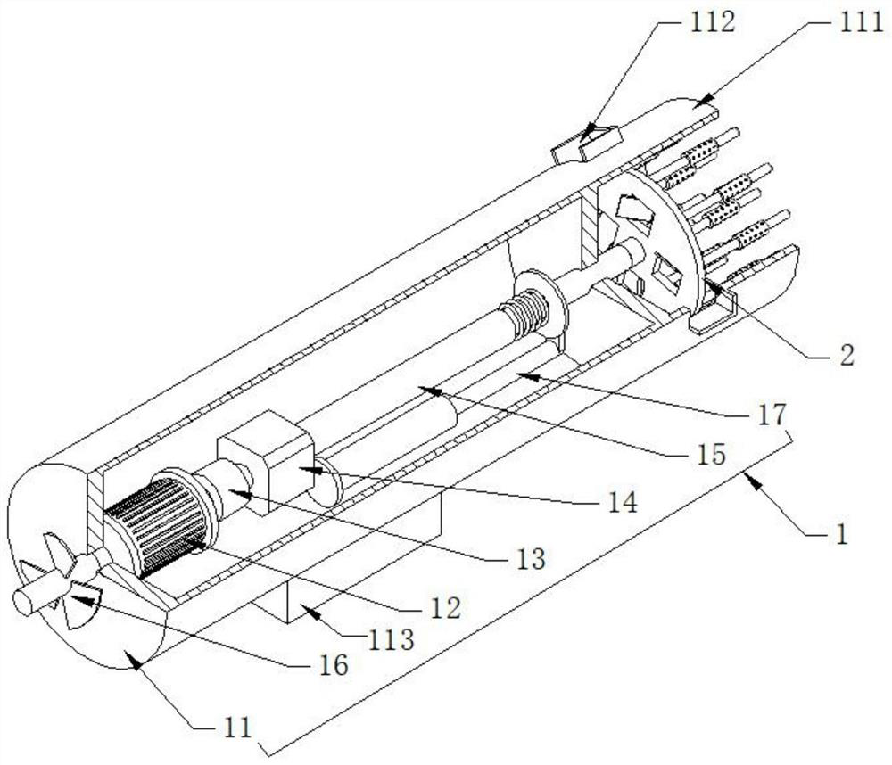
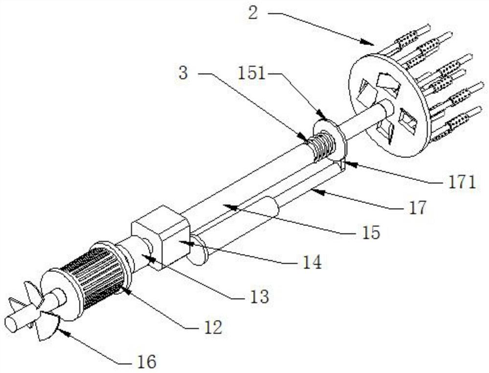
[0037] see Figure 1-5, an underground sludge pipeline dredging device for building construction, comprising a diving part 1 and a loose part 2 arranged at one end of the diving part 1, the diving part 1 includes a diving cylinder 11, a double-head motor 12, an electric clutch 13, and a gear reversing box 14. Telescopic rod 15, cylinder 17 and impeller 16. The impeller 16 is rotated and arranged at one end of the diving tube 11 to provide power for diving and walking. The bottom of the diving tube 11 is fixedly provided with a counterweight box 113. The heavy block is used to adjust the position of the whole diving part 1 in the water. The double-headed motor 12, the electric clutch 13, the gear reversing box 14 and the telescopic rod 15 are all arranged in the diving tube 11 and connected successively along the axial direction. The cylinder 17 is located at Inside the diving tube 11 and its extension shaft is used in conjunction with the action shaft of the telescopic rod 15....

Embodiment 2

[0039] see figure 2 The difference from Embodiment 1 is that the spring 3 is sleeved on the action shaft and on one side of the limit ring plate 151, the traction plate 171 is located on the other side of the limit ring plate 151, and the traction plate 171 is located far away from the spring 3 On one side, when the action shaft shrinks, the spring 3 is in a compressed state. With this structure, after the cylinder 17 is released, the action shaft will protrude outward under the action of the spring 3, and then drive the entire loose part 2 to protrude quickly. The protective limit sleeve 111 and the insertion shaft 2222 on the loose part 2 are inserted into the blockage, and the elastic buffering effect of the spring 3 effectively protects the loose part 2 .

Embodiment 3

[0041] see Figure 4 The difference from Embodiment 1 is that the evaporation part 223 includes a tungsten shaft 2231 located inside and a ceramic sleeve 2232 sleeved outside the tungsten shaft 2231. The ceramic sleeve 2232 and the injection sleeve 222 have a clearance fit, and the tungsten shaft 2231 adopts a metal tungsten shaft 2231. The material has the effect of high temperature resistance. The ceramic sleeve 2232 has good thermal conductivity and can also protect the tungsten shaft 2231.


PUM


Abstract

The invention discloses an underground sludge pipeline dredging device for building construction. The device comprises a diving part and a loosening part arranged at one end of the diving part, wherein the diving part comprises a diving cylinder, a double-head motor, an electric clutch, a gear reversing box, a stretchable rod, an air cylinder and an impeller, and the impeller is rotationally arranged at one end of the diving cylinder. According to the underground sludge pipeline dredging device for the building construction, the diving part carries a jetting part to dive and move in a pluggedblow-down pipeline, the jetting part is inserted into a plugged part, intermediate frequency or high-frequency alternating current is introduced into a high-frequency pipe, the high-frequency pipe generates an alternating magnetic field, induced current with the same frequency is generated in a tungsten shaft, the surface temperature of the tungsten shaft rises to 800-1000 DEG C within a few seconds, water entering a jetting sleeve is rapidly vaporized through a ceramic, and therefore, pressure generated by steam is discharged from jetting holes on the jetting sleeve and enters sludge, and thehigh-pressure steam is used for jetting in the sludge and loosening the sludge, so that the plugged part can be washed away by plugged accumulated water, and the rapid dredging effect is achieved.

Description

technical field [0001] The invention relates to the technical field of building engineering, in particular to an underground sludge pipeline dredging device for building construction. Background technique [0002] In the process of building construction, it is usually necessary to bury sewage pipes underneath to discharge waste water and rainwater generated during building construction to ensure the normal operation of building construction. [0003] However, during building construction, construction waste is prone to appear on the construction site, and construction waste mixed with muddy water is easy to block in the sewage pipe, resulting in pipe blockage, sewage filling, and difficulty in discharging, which in turn affects construction. Most of the existing underground pipe dredging devices are suitable for The working condition of the sewage operation, and the method of artificially diving into the blocked part to dredge it is time-consuming and laborious, and the safe...

Claims


Application Information

Patent Timeline
Patent Type & Authority Patents(China)
IPC IPC(8): E03F9/00F22B1/28
CPCE03F9/005F22B1/28
Inventor 颜彬颜玉龙刘永娇
Owner 秭归福祥建设工程有限公司
Why Eureka
Try Eureka