
Heating device and heating control system for testing high-temperature parameters of power device

A technology for parameter testing and power devices, applied in induction heating control, single semiconductor device testing, measuring devices, etc., can solve the problems of personnel safety threats, easy burns for operators, poor temperature balance of the overall platform, etc., to achieve good temperature balance Effect

Active Publication Date: 2020-02-18
SICHUAN LIPTAI ELECTRONICS
View PDF6 Cites 3 Cited by
  • Summary
  • Abstract
  • Description
  • Claims
  • Application Information

AI Technical Summary

Problems solved by technology

[0003] Therefore, it has the following disadvantages: the use of all-aluminum heating table, because the heating tube is installed inside, the table is very thick, and the overall heating speed is slow. At present, it takes 20-30 minutes to heat to the predetermined temperature (120-150°C); single-sided Heating, the power device under test is heated in contact with the table surface, but the other side of the power device under test is not heated, instead it will dissipate heat, and the actual temperature of the device cannot reach the set temperature value; a single heating tube is used, and there is a local temperature of the heating tube When the temperature is high and the temperature in other places is low, the temperature balance of the overall platform is poor; the device to be tested is fixed to the heating table by bolts, which is not suitable for heating devices without screw holes; Possess a threat; the overall heating table is exposed, which is easy to burn the operator

Method used


Image

  • Heating device and heating control system for testing high-temperature parameters of power device
  • Heating device and heating control system for testing high-temperature parameters of power device
  • Heating device and heating control system for testing high-temperature parameters of power device

Examples


Embodiment Construction

[0029] Hereinafter, the heating device and heating control system for testing high temperature parameters of power devices according to the present invention will be described in detail with reference to the accompanying drawings and exemplary embodiments.

[0030] One aspect of the present invention provides a heating device for testing high temperature parameters of power devices.

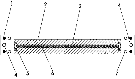
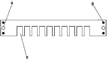
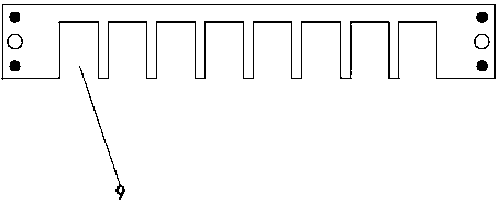
[0031] In an exemplary embodiment of the invention, the heating device may include a first heating layer, a heat resistance test layer and a second heating layer. The first heating layer, the heat-resistant test layer and the second heating layer are arranged sequentially from bottom to top, and from a top view, the three can overlap each other. The first heating layer is provided with a first heating assembly, the heat-resistant test layer is used to place the object to be tested, and the second heating layer is provided with a second heating assembly.

[0032] Specifically, the first heating l...


PUM


Abstract

The invention provides a heating device and a heating control system for testing high-temperature parameters of a power device. The heating device includes a first heating layer, a heat-resistant testlayer, and a second heating layer. The first heating layer includes at least three fixed support members, a first recessed portion, and a first heating component. The first heating component is powered on to be heated so as to heat a to-be-tested piece. The heat-resistant test layer includes at least three through-holes and a to-be-tested piece placement portion. The first heating component is powered on to be heated so as to be able to heat the to-be-tested piece. The second heating layer includes at least three fixing holes, a second recessed portion and a second heating component. The second heating component is powered on to be heated so as to heat the to-be-tested piece in the to-be-tested piece placement portion. The heating control system includes the heating device and a temperature control device. The temperature control device includes a DC power supply component, a switch component, a control component, and a sensing component. The heating device is safe to use, and suitable for testing the power device without a screw hole.

Description

technical field [0001] The invention relates to the field of power device testing, in particular to a heating device and a heating control system for testing high-temperature parameters of power devices. Background technique [0002] At present, the traditional heating table mainly adopts an all-aluminum heating table, which is powered by alternating current for single-sided heating. The power device to be tested is fixed to the heating table by bolts, and the heating temperature is controlled by a temperature controller. [0003] Therefore, it has the following disadvantages: the use of all-aluminum heating table, because the heating tube is installed inside, the table is very thick, and the overall heating speed is slow. At present, it takes 20-30 minutes to heat to the predetermined temperature (120-150°C); single-sided Heating, the power device under test is heated in contact with the table surface, but the other side of the power device under test is not heated, instead...

Claims


Application Information

Patent Timeline
Patent Type & Authority Applications(China)
IPC IPC(8): H05B6/06G01R31/26
CPCG01R31/2601
Inventor 贺勇蔡少峰李科陈凤甫邓波李力杨红伟蒲俊德
Owner SICHUAN LIPTAI ELECTRONICS
Learn More