
Container for optical stereoscopic shaping device

A container and irradiation device technology, which is applied to household containers, chemical instruments and methods, and accessories for processing main materials, etc., can solve problems such as deterioration, shape deformation, and damage to containers, and achieve excellent durability and molding accuracy. Effect

Active Publication Date: 2020-02-18
KURARAY NORITAKE DENTAL
View PDF11 Cites 0 Cited by
  • Summary
  • Abstract
  • Description
  • Claims
  • Application Information

AI Technical Summary

Problems solved by technology

[0004] However, in this lifting method, the shaped object formed on the pedestal is close to the container containing the photocurable composition, so there is a possibility of deformation of the shaped object, damage to the container, etc.
In addition, in various photocurable compositions, there is a problem of deterioration due to damage to the container due to penetration or solidification of the container.

Method used


Image

  • Container for optical stereoscopic shaping device
  • Container for optical stereoscopic shaping device
  • Container for optical stereoscopic shaping device

Examples


Embodiment 1

[0076] A prism made of PMMA with a thickness of 12 mm x width of 30 mm, and a sheet made of PMMA with a thickness of 1.0 mm x 1 side of 244 mm (pencil hardness measured according to JIS K 5600-5-4: 1999 is 3H), and produced a height of 33 mm x 1 side 244mm, bottom thickness 1.0mm, bottom area 484cm 2 of PMMA containers.

[0077] Next, 100 g of KE-103 and 5.0 g of CAT-103 were collected in a disposable cup made of polypropylene, and stirred by hand for about 1 minute using a spatula to obtain Silicone 1. 25 g of the above-mentioned silicone 1 was poured into the above-mentioned container made of PMMA, the whole was spread with a spatula, and after standing for 24 hours, the temperature was raised at 70° C. for 6 hours to form a soft resin layer. The hardness of the soft resin layer measured by JIS K 6253-3:2012 Type A durometer (Aska Rubber Hardness Tester Type A, manufactured by Macromolecular Keiki Co., Ltd.) was 50, and the thickness of the soft resin layer was 0.5 mm.

[...

Embodiment 2

[0080] Except for changing the thickness of the PMMA-made sheet, that is, the thickness of the first layer (X), changing the amount of the silicone 1 flowing into the PMMA-made container to 250 g, and changing the thickness of the FEP sheet to 0.5 mm Otherwise, in the same manner as in Example 1, a container was produced. The hardness of the soft resin layer measured by the JIS K 6253-3:2012 type A durometer was 50, and the thickness of the soft resin layer was 5.0 mm.

Embodiment 3

[0082] PMMA was changed to PC (the pencil hardness of the sheet made of PC measured according to JIS K 5600-5-4:1999 was F), the thickness of the first layer (X) was changed to 3.0 mm, and the silicone 1 was changed For silicone 2, the amount of silicone 2 flowing into the PC-made container was changed to 50 g, and the FEP sheet with a thickness of 0.25 mm was changed into an ETFE sheet with a thickness of 0.75 mm, in the same manner as in Example 1. Make the container in the same way. The hardness of the soft resin layer measured by the JIS K 6253-3:2012 type A durometer was 60, and the thickness of the soft resin layer was 1.0 mm.


PUM

PropertyMeasurementUnit
thicknessaaaaaaaaaa
thicknessaaaaaaaaaa
thicknessaaaaaaaaaa

Abstract

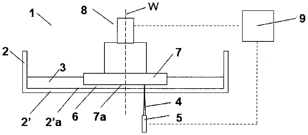
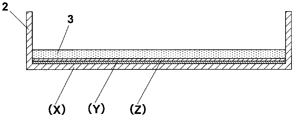
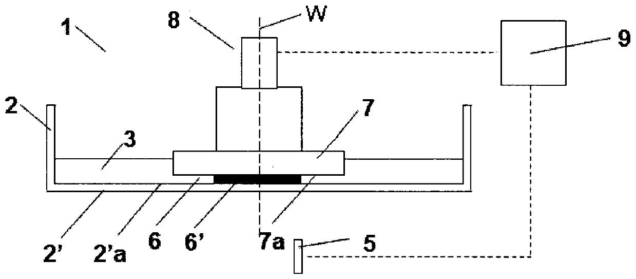
The present invention provides a container which is used for an optical stereoscopic shaping device and has superior transparency, molding accuracy, and durability. The present invention pertains to acontainer for accommodating a photocurable composition (3) used in an optical stereoscopic shaping device provided with a container (2), an active energy ray irradiation device (5), and an actuator (8), the container (2) having a bottom (2') and walls, wherein the bottom (2') is provided with a first layer (X) composed of a hard resin, a second layer (Y) composed of a soft resin, and a third layer (Z) composed of a fluorine resin; the second layer (Y) is laminated on the first layer (X), and the third layer (Z) is laminated on the second layer (Y); the pencil hardness of the first layer (X) is at least 3B as measured according to JIS K 5600-5-4:1999; the hardness of the second layer (Y) is 10-90 as measured by an A durometer according to JIS K 6253-3:2012; and the thickness of the third layer is 0.1-5.0 mm.

Description

technical field [0001] The present invention relates to a container excellent in transparency, molding accuracy and durability used in an optical three-dimensional modeling device. Background technique [0002] Patent Document 1 discloses a method of supplying a necessary amount of controlled light energy to a liquid photocurable resin to cure it into a thin layer, and further supplying a liquid photocurable resin thereon, and then performing the process under control. The lamination is solidified into a thin layer by light irradiation, and the three-dimensional shape is produced by repeating the above steps, which is the so-called optical three-dimensional modeling method. Furthermore, since Patent Document 2 proposed its basic practical method, various proposals related to optical three-dimensional modeling technology have been proposed. [0003] As a typical method of optically producing three-dimensional structures, the following method is generally adopted: the liquid ...

Claims


Application Information

Patent Timeline
Patent Type & Authority Applications(China)
IPC IPC(8): B29C64/255B29C64/135B32B27/00B32B27/30B33Y30/00
CPCB29C64/255B33Y30/00B29C64/124B33Y10/00B32B2307/536B32B27/308B32B25/14B32B7/022B32B2307/412B32B2439/00B32B27/365B32B25/08B32B2307/732B32B1/02B32B27/36B32B27/302B32B27/325B32B27/283B32B27/32B32B2250/03B32B27/08B32B2250/24B33Y40/00B29C64/135B32B27/30
Inventor 铃木宪司坂本紘之
Owner KURARAY NORITAKE DENTAL
Learn More