
Visible hemostatic balloon

A technology of balloon and cavity, applied in medical science, surgery, surgical lighting, etc., can solve the problems of difficult hemostasis, incomplete hemostasis, inaccurate positioning, etc., and achieve the effect of reducing patient discomfort

Pending Publication Date: 2020-02-21
HUBEI KANGQUAN MEDICAL TECH CO LTD
View PDF0 Cites 4 Cited by
  • Summary
  • Abstract
  • Description
  • Claims
  • Application Information

AI Technical Summary

Problems solved by technology

[0003] 1. The stuffing operation is performed under invisible conditions. The positioning of the wound requires extensive experience, otherwise there may be inaccurate positioning and insufficient hemostasis due to compression
[0004] 2. Compression and hemostasis under normal methods need to fill the cavity with materials. In this case, the cavity will lose its function. For example, the nasal cavity will not be able to ventilate. greatly increase
[0005] 3. Generally, the stuffing is performed under anesthesia, and the patient will not feel uncomfortable, but the stuffing is taken out in an awake state. The friction and adhesion between the stuffing and the wound make the process of taking out obvious discomfort
[0006] 4. If there is still bleeding after the packing is taken out, it is more difficult to stop the bleeding again, and it is very likely that a second operation is required
[0007] 5. Due to the rupture of exogenous blood vessels in the cavity, such as the rupture of the nasal artery, the bleeding can be stopped quickly by ordinary pressing, and the bleeding location cannot be quickly found by ordinary packing. It is not conducive to emergency treatment in the emergency department.

Method used


Image

  • Visible hemostatic balloon
  • Visible hemostatic balloon
  • Visible hemostatic balloon

Examples


Embodiment Construction

[0030] The present invention will be further described in detail below in conjunction with the accompanying drawings and specific embodiments.

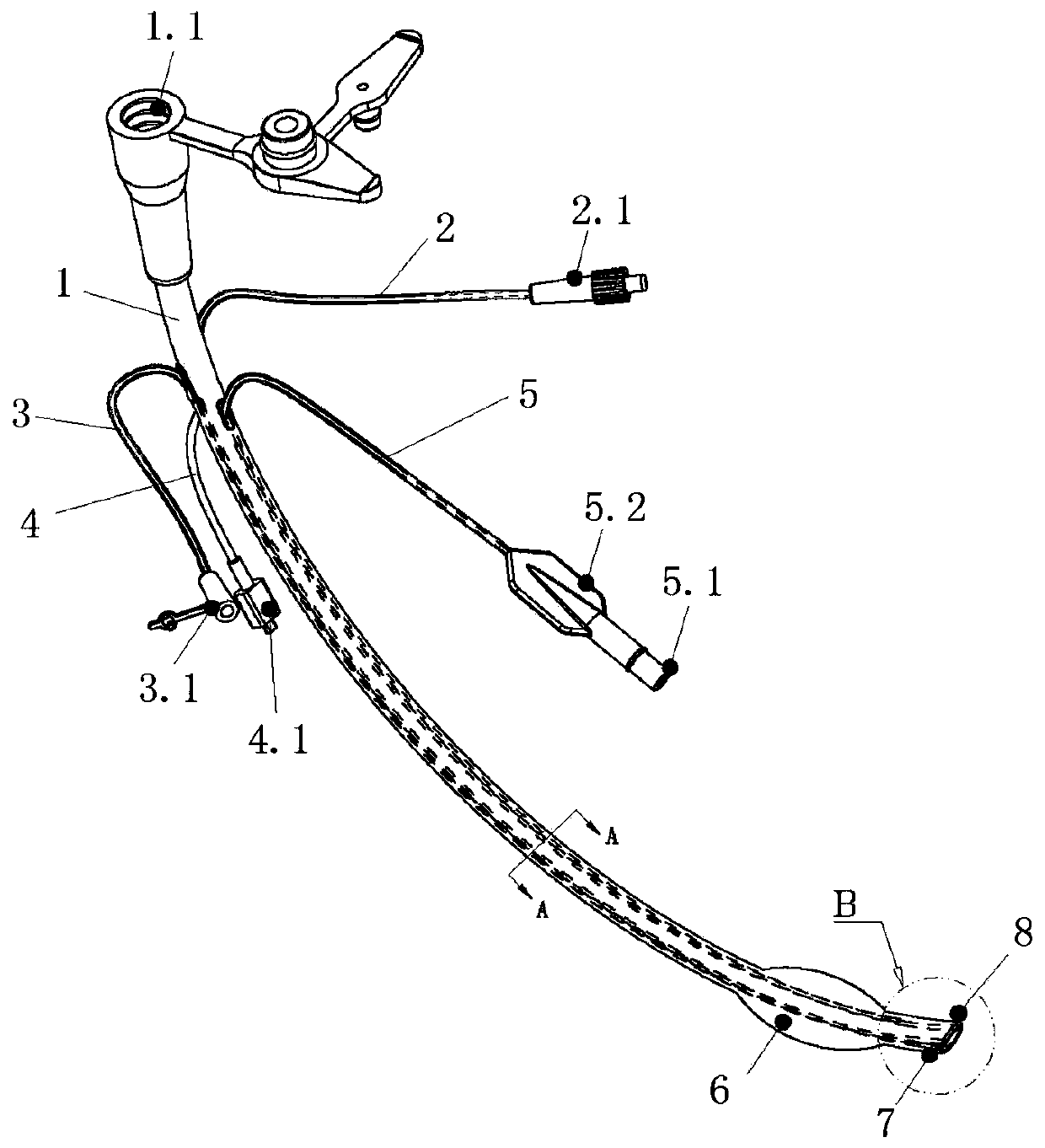
[0031] like figure 1 and figure 2 As shown, the visible hemostatic balloon of the present invention includes a main lumen 1, and the main lumen 1 includes a gripping end ( figure 1 upper middle end) and working end ( figure 1 middle and lower end), the main lumen 1 is surrounded by a hemostatic balloon 6 near the working end, the hemostatic balloon 6 is made of flexible material, can expand after inflated, and can retract after deflated.

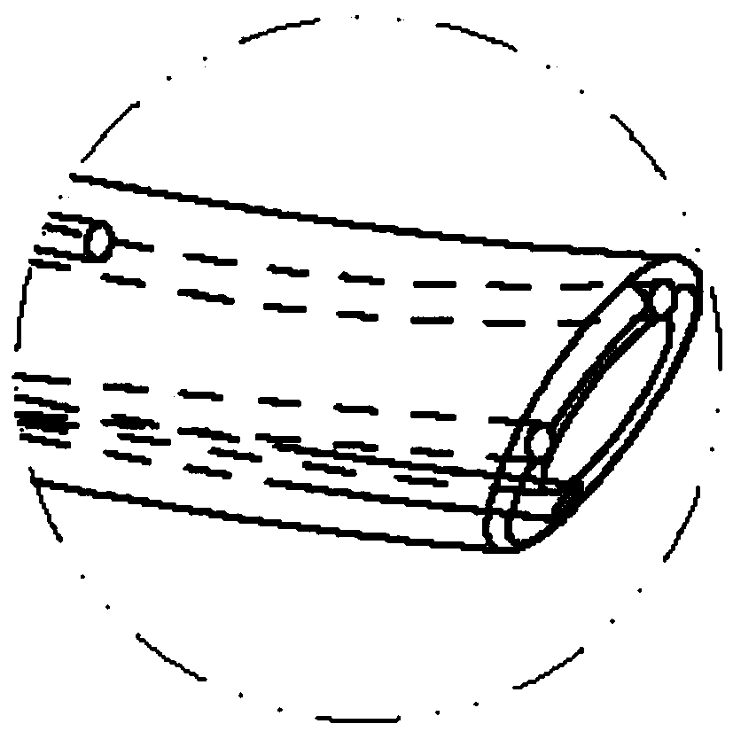
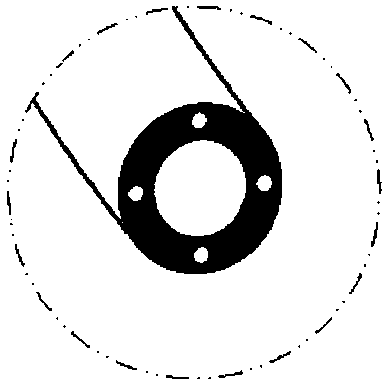
[0032] The main cavity 1 is equipped with an optical fiber cavity 2, a flushing and injection cavity 3, a camera cavity 4 and an inflatable cavity 5, an optical fiber cavity 2, a flushing and injection cavity 3, a camera cavity 4 and an inflatable cavity 5 can be built into the wall of the main lumen 1 respectively, such as image 3 As shown, or set in the main lumen 1 and adhere to the tube wa...


PUM


Abstract

The invention relates to a visible hemostatic balloon, which comprises a main cavity channel, the main cavity channel comprises a holding end and a working end, and the position, close to the workingend, of the main cavity channel is wrapped with the hemostatic balloon; a flushing medicine injection cavity channel, an inflation cavity channel, an optical fiber cavity channel and a camera cavity channel are arranged in the main cavity channel. One ends of the main cavity channel, internally provided with the flushing medicine injection cavity channel, the inflation cavity channel, the opticalfiber cavity channel and the camera cavity channel extend out from the position close to the holding end respectively; and the other ends respectively extend out from the position close to the workingend, then are positioned beside the hemostatic balloon, extend out from the position close to the working end, then are positioned in the hemostatic balloon, and are arranged at the working end or the position close to the working end, or are arranged at the working end or the position close to the working end. The situation of the affected part can be directly observed, bleeding stopping can beconveniently, rapidly and accurately conducted on the affected part, and the affected part cannot adhere to a wound when taken out.

Description

technical field [0001] The invention relates to a hemostatic device, in particular to a visible hemostatic balloon. Background technique [0002] At present, surgical hemostasis in many natural orifices of the human body (such as nasal surgery) usually uses gauze, expansion sponge and other materials for local compression to stop bleeding. Although this method of hemostasis is effective, it also has the following obvious disadvantages: [0003] 1. The operation of packing is performed under invisible conditions. The positioning of the wound requires extensive experience, otherwise there may be inaccurate positioning and insufficient compression and hemostasis. [0004] 2. Compression and hemostasis under common methods need to fill the cavity with materials. In this case, the cavity will lose its function. For example, the nasal cavity will not be able to ventilate. greatly increase. [0005] 3. Generally, the packing is performed under anesthesia, and the patient will not...

Claims


Application Information

Patent Timeline
Patent Type & Authority Applications(China)
IPC IPC(8): A61B17/12A61B17/24A61B90/00A61B90/30
CPCA61B17/12136A61B17/24A61B90/30A61B90/361A61B2017/1205A61B2090/306A61B2090/3614A61B2217/007
Inventor 曹轲
Owner HUBEI KANGQUAN MEDICAL TECH CO LTD
Learn More