
Oral supporting device for minimally invasive apicoectomy

A support device and oral cavity technology, applied in medical science, dentistry, dental nerve needles, etc., to achieve the effect of avoiding cross-infection and convenient operation

Inactive Publication Date: 2020-02-21
BINZHOU MEDICAL COLLEGE
View PDF10 Cites 3 Cited by
  • Summary
  • Abstract
  • Description
  • Claims
  • Application Information

AI Technical Summary

Problems solved by technology

[0003] The purpose of the present invention is to solve the shortcoming in the prior art that the medical personnel need to manually turn up the patient's lips and prop them up for a long time, and propose an oral support device for minimally invasive apexectomy

Method used


Image

  • Oral supporting device for minimally invasive apicoectomy
  • Oral supporting device for minimally invasive apicoectomy
  • Oral supporting device for minimally invasive apicoectomy

Examples


Embodiment 1

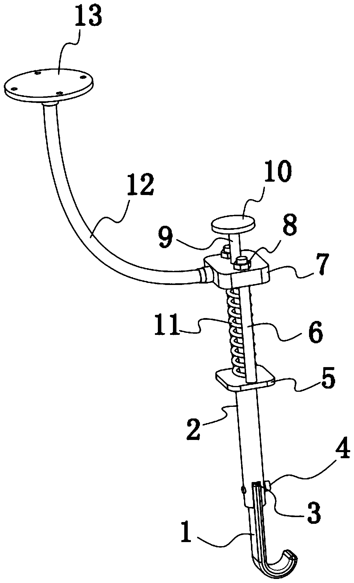
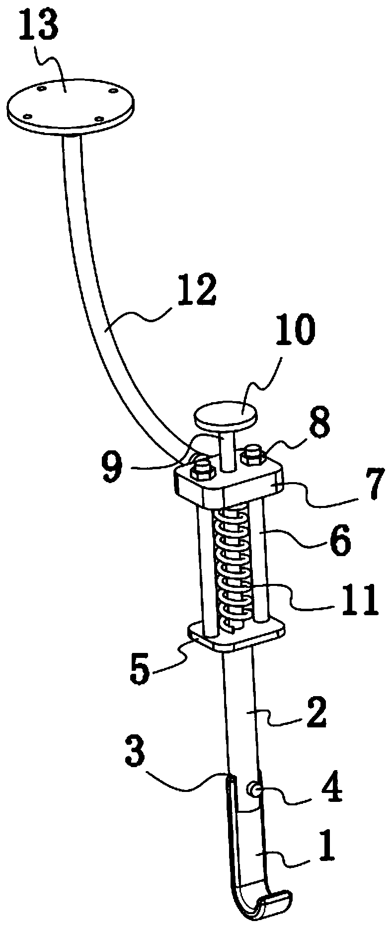
[0016] refer to Figure 1-3 , an oral support device for minimally invasive apicectomy, comprising a fixed column 2, characterized in that the bottom end of the fixed column 2 is provided with a notch 3, and an arc-shaped pick 1 is inserted into the notch 3, and an arc-shaped pick plate 1 It is a disposable plastic dial, and the arc dial 1 is fixedly installed on the fixed column 2 by the screw 4. After performing an operation on the patient, the arc dial 1 can be removed and replaced, thereby effectively avoiding Cross-infection occurs.

[0017] The top of the fixed column 2 is fixedly connected with a first fixed plate 5, and a first threaded column 6 is fixedly installed on both sides of the upper surface of the first fixed plate 5, and a second fixed plate 7 is arranged directly above the first fixed plate 5. The tops of the threaded columns 6 extend upwards until they pass through the second fixed plate 7, and the first threaded column 6 is located on the cylinder above ...

Embodiment 2

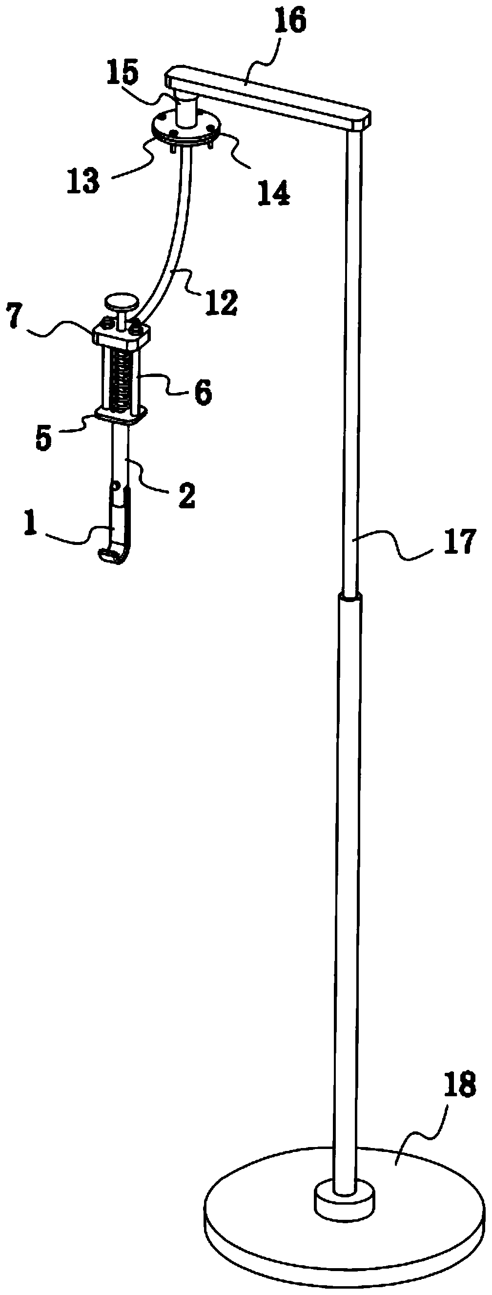
[0021] refer to image 3 , as another preferred embodiment of the present invention, the difference from Embodiment 1 is that the support mechanism includes a second connection plate 14, a rotating shaft 15, a horizontal plate 16, a telescopic rod 17, and a chassis 18, and a telescopic rod is fixedly installed on the chassis 18. 17. A horizontal plate 16 is fixedly installed on the top of the telescopic rod 17, a rotating shaft 15 is fixedly installed on the lower surface of the horizontal plate 16, and a second connecting plate 14 is fixedly installed on the bottom end of the rotating shaft 15, between the second connecting plate 14 and the first connecting plate 13 They are fixed together by several bolts and nuts. By providing the rotating shaft 15 , the further adjustment of the arc dial 1 can be realized by rotating the rotating shaft 15 , and the overall height of the device can be further adjusted by using the telescopic rod 17 .


PUM


Abstract

The invention relates to the technical field of medical instruments, and more particularly to an oral supporting device for minimally invasive apical excision. A notch is formed in the bottom end of afixed column, and an arc-shaped setting piece is inserted into the notch. A second fixed plate is arranged right above the first fixed plate. The top ends of first threaded columns extend upwards through the second fixed plate. A second threaded column is provided to penetrate through the part, between two first threaded columns, of the second fixed plate in a threaded manner; the bottom end of the second threaded column abuts against the upper surface of the first fixed plate; a rotating disc is fixedly mounted on the top end of the second threaded column; a spring sleeves the second threaded column between the second fixed plate and the first fixed plate; a universal bent rod is fixedly mounted on a side face of the second fixed plate; the other end of the universal bent rod is fixedlyconnected with a first connecting disc, and the first connecting disc is fixedly mounted on a supporting mechanism. The oral supporting device for minimally invasive apical excision has the advantageof effectively assisting a doctor to conduct apical excision.

Description

technical field [0001] The invention relates to the technical field of medical instruments, in particular to an oral cavity support device for minimally invasive apexectomy. Background technique [0002] Apicectomy is mainly aimed at chronic apical periodontitis with a large range of inflammatory damage to the root tip. This kind of situation adopts modern root canal treatment technology, and the sinus tract cannot be cured, and the curative effect is unsatisfactory. In order to preserve the affected tooth, apical microsurgery is required. Under the microscope, flap the soft tissue, remove the bone, expose the root tip of the disease, clean the tissue around the root tip and the medullary cavity, resect the root tip of the disease, and seal the root canal system at the root tip with special materials. Finally, the periapical lesion healed and the affected tooth was preserved. When performing apical resection, it is necessary to turn up the patient's lips so that the patie...

Claims


Application Information

Patent Timeline
IPC IPC(8): A61C19/00A61C5/40
CPCA61C19/00A61C5/40
Inventor 荣丽徐军
Owner BINZHOU MEDICAL COLLEGE
Learn More